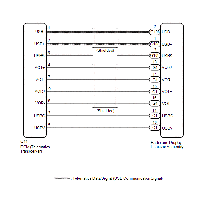
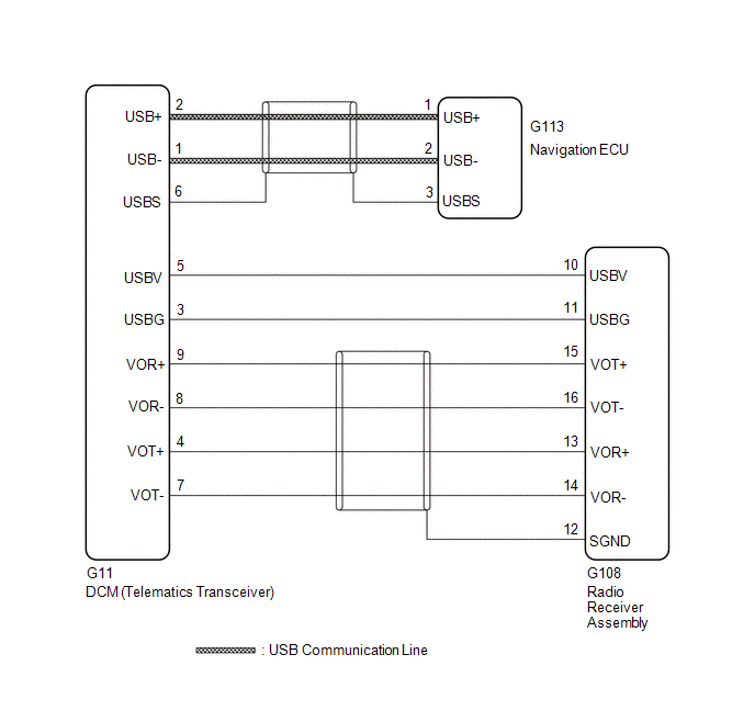
DESCRIPTION This circuit is
used to send and receive signals between the DCM (Telematics
Transceiver) and radio and display receiver assembly. WIRING DIAGRAM w/o Navigation System
 w/ Navigation System w/ Navigation System
 PROCEDURE
(a) Choose the model to be inspected.
| Result |
Proceed to | | w/o Navigation System |
A | | w/ Navigation System |
B |
| B |
 | GO TO STEP 3 |
|
A |
 | |
| 2. |
CHECK HARNESS AND CONNECTOR (RADIO AND DISPLAY RECEIVER ASSEMBLY - DCM (TELEMATICS TRANSCEIVER)) |
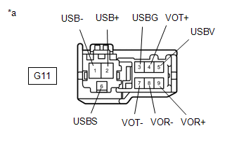
| (a) Disconnect the G11 DCM (Telematics Transceiver) connector. |
 |
|
*a | Front view of wire harness connector
(to DCM (Telematics Transceiver)) | | |
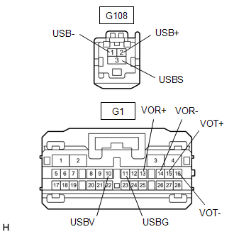
| (b) Disconnect the G1 and G108 radio and display receiver assembly connector. |
 |
|
*a | Front view of wire harness connector
(to Radio and Display Receiver Assembly) | | |
(c) Measure the resistance according to the value(s) in the table below.
Standard Resistance: |
Tester Connection | Condition |
Specified Condition | |
G11-1 (USB-) - G108-2 (USB-) |
Always | Below 1 Ω | |
G11-2 (USB+) - G108-1 (USB+) |
Always | Below 1 Ω | |
G11-6 (USBS) - G108-3 (USBS) |
Always | Below 1 Ω | |
G11-3 (USBG) - G1-11 (USBG) |
Always | Below 1 Ω | |
G11-4 (VOT+) - G1-13 (VOR+) |
Always | Below 1 Ω | |
G11-5 (USBV) - G1-10 (USBV) |
Always | Below 1 Ω | |
G11-7 (VOT-) - G1-14 (VOR-) |
Always | Below 1 Ω | |
G11-8 (VOR-) - G1-16 (VOT-) |
Always | Below 1 Ω | |
G11-9 (VOR+) - G1-15 (VOT+) |
Always | Below 1 Ω | |
G11-1 (USB-) or G108-2 (USB-) - Body ground |
Always | 10 kΩ or higher | |
G11-2 (USB+) or G108-1 (USB+) - Body ground |
Always | 10 kΩ or higher | |
G11-6 (USBS) or G108-3 (USBS) - Body ground |
Always | 10 kΩ or higher | |
G11-3 (USBG) or G1-11 (USBG) - Body ground |
Always | 10 kΩ or higher | |
G11-4 (VOT+) or G1-13 (VOR+) - Body ground |
Always | 10 kΩ or higher | |
G11-5 (USBV) or G1-10 (USBV) - Body ground |
Always | 10 kΩ or higher | |
G11-7 (VOT-) or G1-14 (VOR-) - Body ground |
Always | 10 kΩ or higher | |
G11-8 (VOR-) or G1-16 (VOT-) - Body ground |
Always | 10 kΩ or higher | |
G11-9 (VOR+) or G1-15 (VOT+) - Body ground |
Always | 10 kΩ or higher |
| OK |
| PROCEED TO NEXT SUSPECTED AREA SHOWN IN PROBLEM SYMPTOMS TABLE |
| NG |
| REPAIR OR REPLACE HARNESS OR CONNECTOR |
| 3. |
CHECK HARNESS AND CONNECTOR (RADIO AND DISPLAY RECEIVER ASSEMBLY - DCM (TELEMATICS TRANSCEIVER)) |
(a) Disconnect the G11 DCM (Telematics Transceiver) connector. (b) Disconnect the G108 radio and display receiver assembly connector.
(c) Measure the resistance according to the value(s) in the table below.
Standard Resistance: |
Tester Connection | Condition |
Specified Condition | |
G11-3 (USBG) - G108-11 (USBG) |
Always | Below 1 Ω | |
G11-4 (VOT+) - G108-13 (VOR+) |
Always | Below 1 Ω | |
G11-5 (USBV) - G108-10 (USBV) |
Always | Below 1 Ω | |
G11-7 (VOT-) - G108-14 (VOR-) |
Always | Below 1 Ω | |
G11-8 (VOR-) - G108-16 (VOT-) |
Always | Below 1 Ω | |
G11-9 (VOR+) - G108-26 (VOT+) |
Always | Below 1 Ω | |
G11-3 (USBG) or G108-11 (USBG) - Body ground |
Always | 10 kΩ or higher | |
G11-4 (VOT+) or G108-13 (VOR+) - Body ground |
Always | 10 kΩ or higher | |
G11-5 (USBV) or G108-10 (USBV) - Body ground |
Always | 10 kΩ or higher | |
G11-7 (VOT-) or G108-14 (VOR-) - Body ground |
Always | 10 kΩ or higher | |
G11-8 (VOR-) or G108-16 (VOT-) - Body ground |
Always | 10 kΩ or higher | |
G11-9 (VOR+) or G108-26 (VOT+) - Body ground |
Always | 10 kΩ or higher |
| NG |
| REPAIR OR REPLACE HARNESS OR CONNECTOR |
|
OK | |
| |
| 4. |
CHECK HARNESS AND CONNECTOR (NAVIGATION ECU - DCM (TELEMATICS TRANSCEIVER)) |
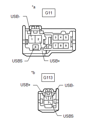
| (a) Disconnect the G11 DCM (Telematics Transceiver) connector. |
 |
|
*a | Front view of wire harness connector
(to DCM (Telematics Transceiver)) | |
*b | Front view of wire harness connector
(to Navigation ECU) | | |
(b) Disconnect the G113 navigation ECU connector. (c) Measure the resistance according to the value(s) in the table below.
Standard Resistance: |
Tester Connection | Condition |
Specified Condition | |
G11-1 (USB-) - G113-2 (USB-) |
Always | Below 1 Ω | |
G11-2 (USB+) - G113-1 (USB+) |
Always | Below 1 Ω | |
G11-6 (USBS) - G113-3 (USBS) |
Always | Below 1 Ω | |
G11-1 (USB-) or G113-2 (USB-) - Body ground |
Always | 10 kΩ or higher | |
G11-2 (USB+) or G113-1 (USB+) - Body ground |
Always | 10 kΩ or higher | |
G11-6 (USBS) or G113-3 (USBS) - Body ground |
Always | 10 kΩ or higher |
| OK |
| PROCEED TO NEXT SUSPECTED AREA SHOWN IN PROBLEM SYMPTOMS TABLE |
| NG |
| REPAIR OR REPLACE HARNESS OR CONNECTOR | | 

