DESCRIPTION When the theft deterrent system is switched from the armed state to the alarm sounding state, the main body ECU (multiplex network body ECU) transmits a signal to cause the horns to sound at intervals of 0.4 seconds. WIRING DIAGRAM 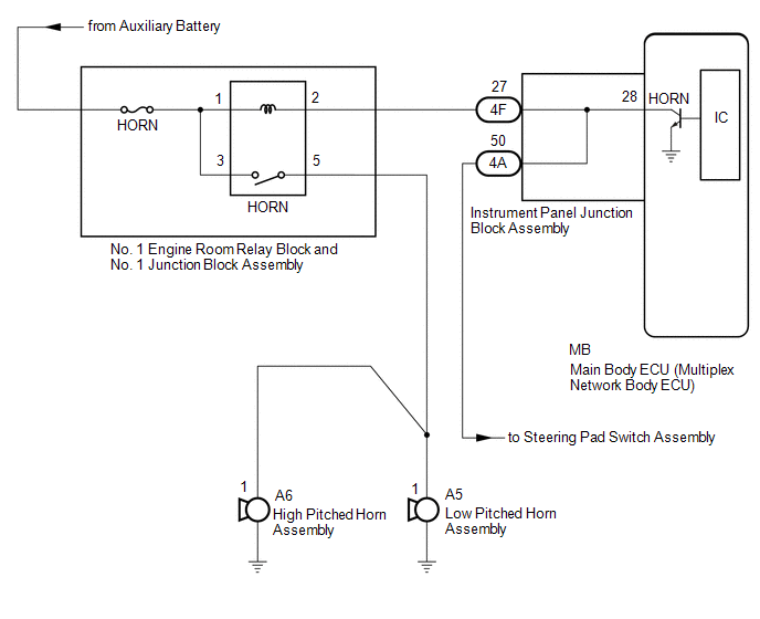 CAUTION / NOTICE / HINT NOTICE:
PROCEDURE
(a) Press the horn switch and check if the horns sound.
(a) Remove the main body ECU (multiplex network body ECU). Click here
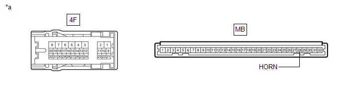
(b) Disconnect the 4F instrument panel junction block assembly connector. (c) Measure the resistance according to the value(s) in the table below. Standard Resistance:
|
Toyota Avalon (XX50) 2019-2022 Owners Manual > Intelligent Clearance
Sonar (ICS): Intelligent Clearance Sonar function
If the Intelligent Clearance Sonar function detects that a collision with an object is possible, the engine output will be restricted to restrain any increase in the vehicle speed. (Engine output restriction control: See A below.) Additionally, if the accelerator pedal continues to be depressed, the ...


