Toyota Avalon Service & Repair Manual: Terminals Of Ecu

TERMINALS OF ECU

DCM (TELEMATICS TRANSCEIVER)

*a

to Telephone Antenna (Sub)

*b

to Telephone Antenna (Main)

*c

to GPS Antenna

-

-

Terminal No. (Symbol)

Wiring Color

Terminal Description

Condition

Specified Condition

G11-1 (USB-)

GR

USB communication line

-

-

G11-2 (USB+)

GR

USB communication line

-

-

G11-6 (USBS) - Body ground

Shielded - Body ground

Shield ground

Always

Below 1 Ω

G11-3 (USBG) - Body ground

GR - Body ground

DCM (Telematics Transceiver) power supply ground signal

Always

Below 1 Ω

G11-4 (VOT+) - G9-4 (E)

R - BR

Sent voice signal

Calling while using the operator service

A waveform synchronized with the voice signals received voice is output

G11-5 (USBV) - G9-4 (E)

L - BR

DCM (Telematics Transceiver) power supply signal

Power switch off

Below 1 V

Power switch on (IG)

4.5 to 5.25 V

G11-7 (VOT-) - G9-4 (E)

G - BR

Sent voice signal

Calling while using the operator service

A waveform synchronized with the received voice is output

G11-8 (VOR-) - G9-4 (E)

W - BR

Receive voice signal

Receiving a call while using the operator service

A waveform synchronized with the sent voice is output

G11-9 (VOR+) - G9-4 (E)

B - BR

Receive voice signal

Receiving a call while using the operator service

A waveform synchronized with the sent voice is output

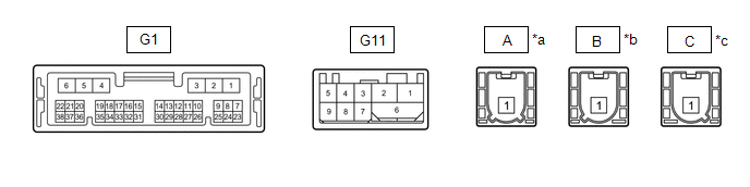
RADIO AND DISPLAY RECEIVER ASSEMBLY

Terminal No. (Symbol)

Wiring Color

Terminal Description

Condition

Specified Condition

G108-2 (USB-)*

BR

USB communication line

-

-

G108-1 (USB+)*

V

USB communication line

-

-

G108-3 (USBS) - Body ground*

Shielded - Body ground

Shield ground

Always

Below 1 V

G1-15 (VOT+) - G3-1 (GND1)

B - BR

Sent voice signal

Destination assist service in use and vehicle occupant speaking to operator

A waveform synchronized with the sent voice is output

G1-10 (USBV) - G3-1 (GND1)

L - BR

DCM (Telematics transceiver) power supply

Power switch on (ACC)

4.75 to 5.25 V

Power switch off

A waveform synchronized with sound is output

G1-16 (VOT-) - G3-1 (GND1)

W - BR

Sent voice signal

Destination assist service in use and vehicle occupant speaking to operator

A waveform synchronized with the sent voice is output

G1-14 (VOR-) - G3-1 (GND1)

G - BR

Receive voice signal

Destination assist service in use and operator speaking to vehicle occupant

A waveform synchronized with the received voice is output

G1-13 (VOR+) - G3-1 (GND1)

R - BR

Receive voice signal

Destination assist service in use and operator speaking to vehicle occupant

A waveform synchronized with the received voice is output

  • *: w/o Navigation System

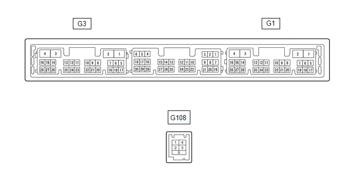
NAVIGATION ECU (w/ Navigation System)

Terminal No. (Symbol)

Wiring Color

Terminal Description

Condition

Specified Condition

G113-2 (USB-)

BR

USB communication line

-

-

G113-1 (USB+)

V

USB communication line

-

-

G113-3 (USBS) - Body ground

Shielded - Body ground

Shield ground

Always

Below 1 V

    System Diagram

    Garage Door Opener

    See More:

    Toyota Avalon Service & Repair Manual > Lane Departure Alert System (w/ Steering Control)(for Hv Model): Diagnostic Trouble Code Chart
    DIAGNOSTIC TROUBLE CODE CHART Lane Departure Alert System (w/ Steering Control) DTC No. Detection Item Link C1A01 Driving Support ECU C1A10 Front Radar Sensor C1A11 Front Radar Sensor Incorrect Axial Gap C1A14 Front Radar Sensor Beam Axis Not Adjusted C1A47 Steering Angle Sensor C1A48 G Sensor C1A50 ...

    Toyota Avalon Owners Manual

    Toyota Avalon Service & Repair Manual

    © 2024 Copyright www.tavalon.net
    0.0139