Toyota Avalon (XX50) 2019-2022 Service & Repair Manual: Extension Module Disconnected 2 (B1543)

DESCRIPTION

If the radio and display receiver assembly cannot detect the navigation ECU for a certain period of time (90 seconds) after the engine switch is turned on (ACC) and the radio and display receiver assembly confirms that the information is missing by checking past navigation ECU recognition information (registered information), this DTC will be stored.

HINT:

The Navigation system uses USB communication between devices. If an open, short, short to +B or short to ground occurs in the USB circuit, communication is interrupted and the Navigation system will not operate normally.

DTC No.

Detection Item

DTC Detection Condition

Trouble Area

B1543

Extension Module Disconnected 2

Navigation ECU disconnected

  • Navigation ECU
  • Radio and display receiver assembly
  • Harness or connector

HINT:

This DTC may be stored due to environmental reasons such as electrical noise or interference.

WIRING DIAGRAM

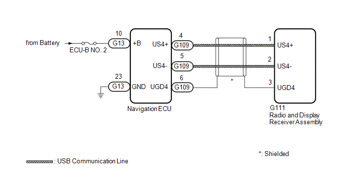
CAUTION / NOTICE / HINT

NOTICE:

  • Depending on the parts that are replaced during vehicle inspection or maintenance, performing initialization, registration or calibration may be needed. Refer to Precaution for Navigation System.

    Click here

  • Inspect the fuses for circuits related to this system before performing the following procedure.
  • When replacing the radio and display receiver assembly or navigation ECU, always replace it with a new one. If a radio and display receiver assembly or navigation ECU which was installed to another vehicle is used, the following may occur:
    • A communication malfunction DTC may be stored.
    • The radio and display receiver assembly or navigation ECU may not operate normally.

PROCEDURE

1.

CHECK MAP SCREEN

(a) Turn the engine switch on (ACC) and wait for 90 seconds.

(b) Press the "MAP" switch and check that the map screen is displayed normally.

Result

Proceed to

Map screen is displayed normally

A

Map screen is not displayed normally

B

HINT:

  • This DTC may be stored due to environmental reasons such as electrical noise or interference.
  • Clear past DTCs when the map screen is displayed normally. (Codes stored due to past environmental factors)
A

USE SIMULATION METHOD TO CHECK

B

2.

CHECK DTC

(a) Clear the DTCs.

Body Electrical > Navigation System > Clear DTCs

(b) Turn the engine switch off.

(c) Turn the engine switch on (IG) and wait for 90 seconds.

(d) Recheck for DTCs and check that no DTCs are output.

Body Electrical > Navigation System > Trouble Codes

OK:

No DTCs are output.

OK

USE SIMULATION METHOD TO CHECK

NG

3.

CHECK HARNESS AND CONNECTOR (NAVIGATION ECU - BATTERY AND BODY GROUND)

(a) Disconnect the G13 navigation ECU connector.

*a

Front view of wire harness connector

(to Navigation ECU)

(b) Measure the resistance according to the value(s) in the table below.

Standard Resistance:

Tester Connection

Condition

Specified Condition

G13-23 (GND) - Body ground

Always

Below 1 Ω

(c) Measure the voltage according to the value(s) in the table below.

Standard Voltage:

Tester Connection

Condition

Specified Condition

G13-10 (+B) - Body ground

Always

11 to 14 V

NG

REPAIR OR REPLACE HARNESS OR CONNECTOR

OK

4.

CHECK HARNESS AND CONNECTOR (RADIO AND DISPLAY RECEIVER ASSEMBLY - NAVIGATION ECU)

(a) Disconnect the G109 navigation ECU connector.

*a

Front view of wire harness connector

(to Radio and Display Receiver Assembly)

*b

Front view of wire harness connector

(to Navigation ECU)

(b) Disconnect the G111 radio and display receiver assembly connector.

(c) Measure the resistance according to the value(s) in the table below.

Standard Resistance:

Tester Connection

Condition

Specified Condition

G109-4 (US4+) - G111-1 (US4+)

Always

Below 1 Ω

G109-5 (US4-) - G111-2 (US4-)

Always

Below 1 Ω

G109-6 (UGD4) - G111-3 (UGD4)

Always

Below 1 Ω

NG

REPAIR OR REPLACE HARNESS OR CONNECTOR

OK

5.

REPLACE NAVIGATION ECU

(a) Replace the navigation ECU with a new one.

Click here

NEXT

6.

CHECK DTC

(a) Clear the DTCs.

Body Electrical > Navigation System > Clear DTCs

(b) Turn the engine switch off.

(c) Turn the engine switch on (IG) and wait for 90 seconds.

(d) Recheck for DTCs and check that no DTCs are output.

Body Electrical > Navigation System > Trouble Codes

OK:

No DTCs are output.

OK

END (NAVIGATION ECU IS DEFECTIVE)

NG

REPLACE RADIO AND DISPLAY RECEIVER ASSEMBLY

    Lost Communication with Meter (B1324,B1325)

    HD Radio Tuner Malfunction (B1551,B158D,B15A0,B15B0,B15B3,B15B7,B15BA,B15F9)

    See More:

    Toyota Avalon (XX50) 2019-2022 Service & Repair Manual > Dynamic Radar Cruise Control System(for Gasoline Model): Front Radar Sensor (C1A10)
    DESCRIPTION The driving support ECU assembly uses the millimeter wave radar sensor assembly to detect obstacles in front of the vehicle. When the driving support ECU assembly receives information that there is a malfunction in the millimeter wave radar sensor assembly, DTC C1A10 is stored. DTC No. D ...

    Toyota Avalon (XX50) 2019-2022 Owners Manual

    Toyota Avalon (XX50) 2019-2022 Service & Repair Manual

    © 2024 Copyright www.tavalon.net
    0.0155