Toyota Avalon Service & Repair Manual: Data Signal Circuit between Radio Receiver and Stereo Jack Adapter

DESCRIPTION

The stereo jack adapter assembly sends the sound data signal or image data signal from a USB device to the radio and display receiver assembly via this circuit.

WIRING DIAGRAM
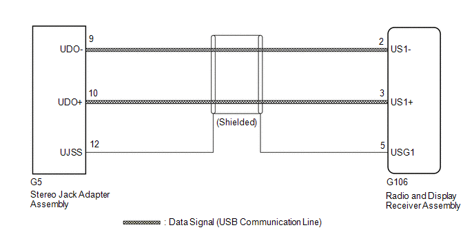
PROCEDURE

1.

CHECK HARNESS AND CONNECTOR (RADIO AND DISPLAY RECEIVER ASSEMBLY - STEREO JACK ADAPTER ASSEMBLY)

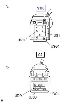
(a) Disconnect the G106 radio and display receiver assembly connector.

(b) Disconnect the G5 stereo jack adapter assembly connector.

(c) Measure the resistance according to the value(s) in the table below.

Standard Resistance:

Tester Connection

Condition

Specified Condition

G106-2 (US1-) - G5-9 (UDO-)

Always

Below 1 Ω

G106-3 (US1+) - G5-10 (UDO+)

Always

Below 1 Ω

G106-5 (USG1) - G5-12 (UJSS)

Always

Below 1 Ω

G106-2 (US1-) or G5-9 (UDO-) - Body ground

Always

10 kΩ or higher

G106-3 (US1+) or G5-10 (UDO+) - Body ground

Always

10 kΩ or higher

G106-5 (USG1) or G5-12 (UJSS) - Body ground

Always

10 kΩ or higher

*a

Front view of wire harness connector

(to Radio and Display Receiver Assembly)

*b

Front view of wire harness connector

(to Stereo Jack Adapter Assembly)

OK

PROCEED TO NEXT SUSPECTED AREA SHOWN IN PROBLEM SYMPTOMS TABLE

NG

REPAIR OR REPLACE HARNESS OR CONNECTOR

    Data List / Active Test

    Diagnostic Trouble Code Chart

    See More:

    Toyota Avalon Service & Repair Manual > Rear Lower Arm: Installation
    INSTALLATION CAUTION / NOTICE / HINT HINT: Use the same procedure for the RH side and LH side. The following procedure is for the LH side. PROCEDURE 1. TEMPORARILY INSTALL REAR NO. 1 SUSPENSION ARM ASSEMBLY (a) Temporarily install the rear No. 1 suspension arm assembly to the rear axle carrier sub-a ...

    Toyota Avalon Owners Manual

    Toyota Avalon Service & Repair Manual

    © 2023 Copyright www.tavalon.net
    0.0183