DESCRIPTION Power is supplied to the radio and display receiver assembly and steering pad switch assembly illumination when the light control switch is in the tail or head position. WIRING DIAGRAM 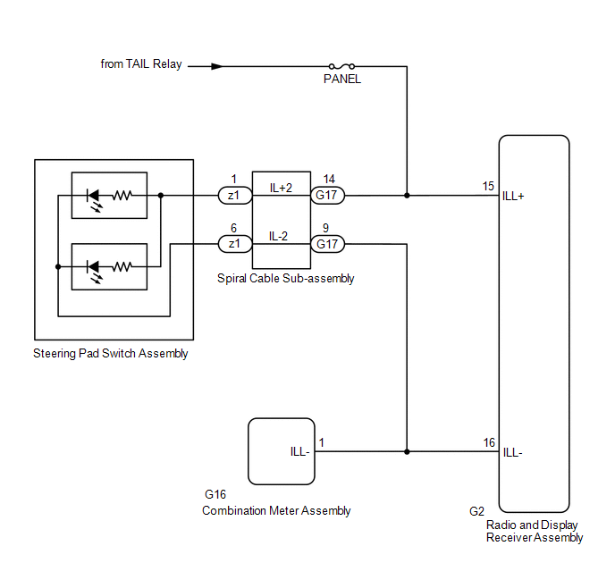 CAUTION / NOTICE / HINT NOTICE:
PROCEDURE
(a) Check if the illumination for the radio and display receiver assembly, steering pad switch assembly, heater control switch or others (hazard switch, transmission control switch, etc.) comes on when the light control switch is turned to the head or tail position.
(a) Disconnect the G17 spiral cable sub-assembly connector. (b) Measure the voltage according to the value(s) in the table below. Standard Voltage:
(a) Remove the steering pad switch assembly. Click here (b) Inspect the steering pad switch assembly. Click here
(a) Remove the spiral cable sub-assembly. Click here (b) Inspect the spiral cable sub-assembly. Click here
(a) Disconnect the G2 radio and display receiver assembly connector. (b) Measure the voltage according to the value(s) in the table below. Standard Voltage:
(a) Disconnect the G2 radio and display receiver assembly connector. (b) Disconnect the G16 combination meter assembly connector. (c) Measure the resistance according to the value(s) in the table below. Standard Resistance:
|
Toyota Avalon (XX50) 2019-2022 Service & Repair Manual > Side Airbag Sensor(for Front Door): On-vehicle Inspection
ON-VEHICLE INSPECTION CAUTION / NOTICE / HINT CAUTION: Be sure to correctly follow the removal and installation procedures for the side airbag pressure sensors. PROCEDURE 1. INSPECT SIDE AIRBAG PRESSURE SENSOR (for Vehicle not Involved in Collision) (a) Perform a diagnostic system check. for Gasolin ...


