DESCRIPTION This is the power source circuit to operate the radio and display receiver assembly. WIRING DIAGRAM 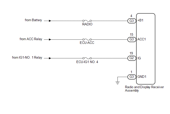 CAUTION / NOTICE / HINT NOTICE: Inspect the fuses for circuits related to this system before performing the following procedure. PROCEDURE
(a) Disconnect the G3 and G2 radio and display receiver assembly connectors. (b) Measure the resistance according to the value(s) in the table below. Standard Resistance:
(c) Measure the voltage according to the value(s) in the table below. Standard Voltage:
|
Toyota Avalon (XX50) 2019-2022 Service & Repair Manual > Wireless Door Lock Control System(for Gasoline Model): Parts Location
PARTS LOCATION ILLUSTRATION *1 HEADLIGHT ASSEMBLY RH - TURN SIGNAL LIGHT *2 HEADLIGHT ASSEMBLY LH - TURN SIGNAL LIGHT *3 SIDE TURN SIGNAL LIGHT ASSEMBLY RH *4 SIDE TURN SIGNAL LIGHT ASSEMBLY LH *5 REAR COMBINATION LIGHT ASSEMBLY RH - TURN SIGNAL LIGHT *6 REAR COMBINATION LIGHT ASSEMBLY LH - TURN SIG ...


