DESCRIPTION This circuit includes the navigation ECU and radio and display receiver assembly. WIRING DIAGRAM 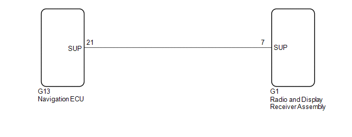 PROCEDURE
(a) Disconnect the G1 radio and display receiver assembly connector. (b) Disconnect the G13 navigation ECU connector. (c) Measure the resistance according to the value(s) in the table below. Standard Resistance:
|
Toyota Avalon (XX50) 2019-2022 Service & Repair Manual > Condenser: Components
COMPONENTS ILLUSTRATION *1 FRONT BUMPER ENERGY ABSORBER *2 FRONT BUMPER REINFORCEMENT *3 NO. 2 FRONT BUMPER ENERGY ABSORBER *4 UPPER RADIATOR MOUNTING BRACKET N*m (kgf*cm, ft.*lbf): Specified torque - - ILLUSTRATION *A for 2GR-FKS *B for A25A-FXS *1 HOOD LOCK ASSEMBLY *2 INLET AIR CLEANER ASSEMBLY * ...


