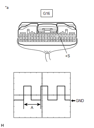
DESCRIPTION The navigation ECU receives a vehicle speed signal from the combination meter assembly. HINT:
WIRING DIAGRAM 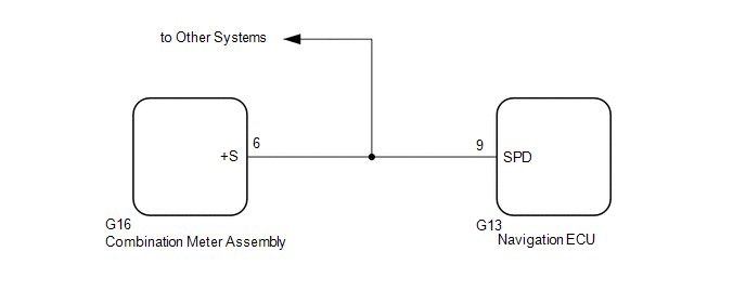 PROCEDURE
(a) Disconnect the G13 navigation ECU connector. (b) Disconnect the G16 combination meter assembly connector. (c) Measure the resistance according to the value(s) in the table below. Standard Resistance:
|
Toyota Avalon (XX50) 2019-2022 Service & Repair Manual > Parking Assist Monitor System(for Gasoline Model): Back Camera Power Supply Failure (C1621)
DESCRIPTION This DTC is stored if the television camera assembly judges as a result of its self check that the signals or signal lines between the television camera assembly and radio and display assembly are not normal. DTC No. Detection Item DTC Detection Condition Trouble Area C1621 Back Camera P ...