DESCRIPTION This circuit is used when the voice switch of the steering pad switch assembly is pushed. Using this circuit, the radio and display receiver assembly sends signals to the stereo component amplifier assembly. WIRING DIAGRAM 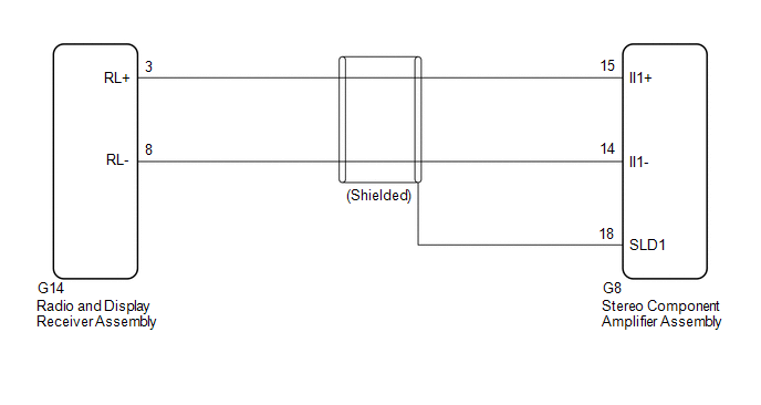 PROCEDURE
(a) Disconnect the G14 radio and display receiver assembly connector. (b) Disconnect the G8 stereo component amplifier assembly connector. (c) Measure the resistance according to the value(s) in the table below. Standard Resistance:
|
Toyota Avalon (XX50) 2019-2022 Service & Repair Manual > Motor Generator Control System: Generator Inverter Stuck On (P0A7A9E,P1C5F19)
DTC SUMMARY MALFUNCTION DESCRIPTION This DTC indicates that a large current flowed in the inverter generator. The cause of this malfunction may be one of the following: Area Main Malfunction Description Hybrid vehicle transaxle assembly Open or short circuit in the generator coils Generator (MG1) in ...


