|
Sender | Receiver |
Signal | Line |
|
Main Body ECU (Multiplex Network Body ECU) |
Clearance Warning ECU Assembly | Destination information signal |
CAN Communication Line |
| ECM |
Clearance Warning ECU Assembly | Shift position signal |
CAN Communication Line |
| Combination Meter Assembly |
Clearance Warning ECU Assembly | Vehicle speed signal |
CAN Communication Line |
| Clearance Warning ECU Assembly |
Combination Meter Assembly |
- Sonar information signal
- Clearance sonar indicator illumination request signal
| CAN Communication Line |
|
Clearance Warning ECU Assembly | Television Camera Assembly*2 |
Sonar information signal | CAN Communication Line |
|
Clearance Warning ECU Assembly | Parking Assist ECU*1 |
Sonar information signal | CAN Communication Line |
|
Parking Assist ECU*1 | Radio and Display Receiver Assembly |
Video signal | Analog |
|
Television Camera Assembly*2 |
Radio and Display Receiver Assembly |
Video signal | Analog |
|
Clearance Warning ECU Assembly |
Headup Display (Meter Mirror Sub-assembly)*3 |
Sonar information signal |
CAN Communication Line |
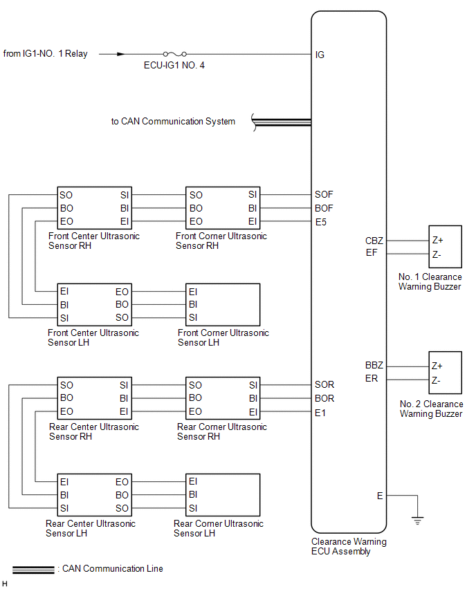
 Communication Table

