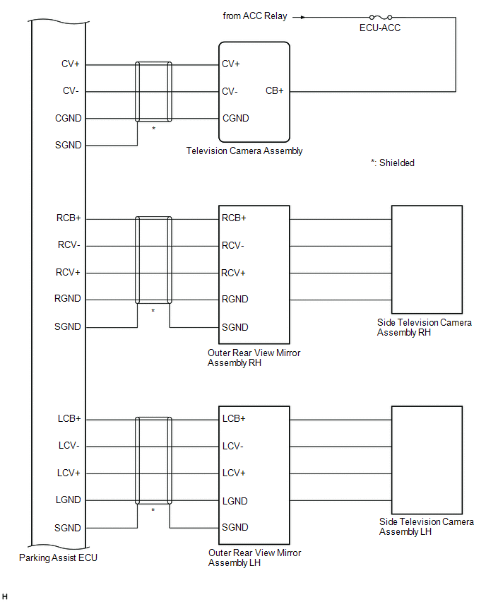
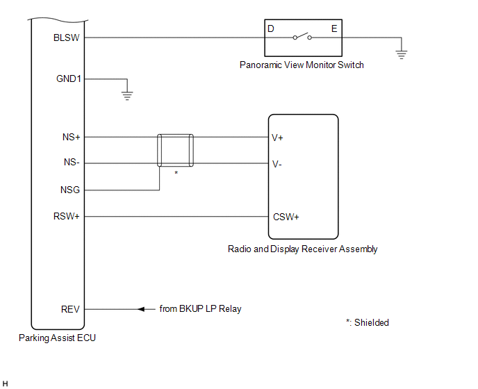
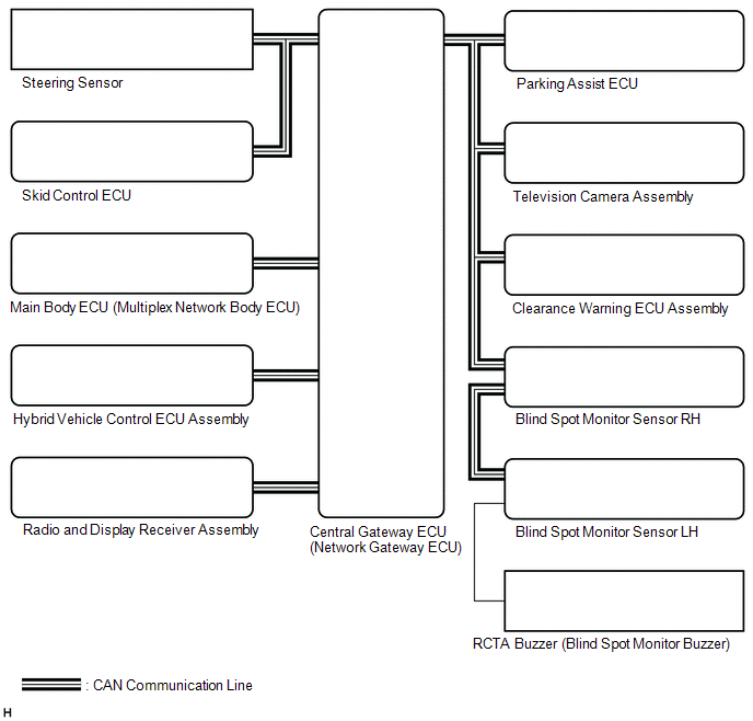
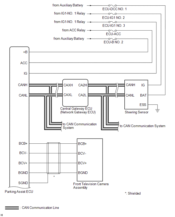
Toyota Avalon Service & Repair Manual: System Diagram

SYSTEM DIAGRAM

Sender

Receiver

Signal

Line

Steering Sensor

Parking Assist ECU

  • Data continuity flag
  • Steering angle signal

CAN

Skid Control ECU

Parking Assist ECU

  • Wheel speed signal
  • Vehicle speed signal

CAN

Main Body ECU (Multiplex Network Body ECU)

Parking Assist ECU

  • Courtesy light switch signal
  • Outer mirror retract information
  • Destination signal
  • Steering wheel signal
  • Vehicle information

CAN

Hybrid Vehicle Control ECU Assembly

Parking Assist ECU

  • Shift lever position signal
  • Drivetrain information
  • 2WD/AWD information
  • HV flag

CAN

Clearance Warning ECU Assembly

Parking Assist ECU

Sonar information signal

CAN

Blind Spot Monitor Sensor RH

  • Parking Assist ECU
  • Television Camera Assembly

RCTA information signal

CAN

Television Camera Assembly

Blind Spot Monitor Sensor RH

Camera detection buzzer request

CAN

    System Description

    Terminals Of Ecu

    See More:

    Toyota Avalon Service & Repair Manual > Audio And Visual System(for Hv Model): AVC-LAN Circuit
    DESCRIPTION Each unit of the audio and visual system connected to the AVC-LAN (communication bus) transmits signals via AVC-LAN communication. If a short to +B or short to ground occurs in an AVC-LAN communication line, the audio and visual system will not function normally because communication is ...

    Toyota Avalon Owners Manual

    Toyota Avalon Service & Repair Manual

    © 2023 Copyright www.tavalon.net
    0.0124