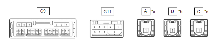
TERMINALS OF ECU HINT: Check from the rear of the connector while it is connected to the components.
DCM (TELEMATICS TRANSCEIVER)
|
*a | to Telephone Antenna (Sub) |
*b | to Telephone Antenna (Main) | |
*c | to GPS Antenna |
- | - | |
Terminal No. (Symbol) | Wiring Color |
Terminal Description | Condition |
Specified Condition | |
G9-1 (+B) - G9-4 (E) |
B - W-B | Power source (+B) |
Always | 11 to 14 V | |
G9-4 (E) - Body ground |
W-B - Body ground | Ground |
Always | Below 1 V | |
G9-7 (IG2) - G9-4 (E) |
LG - W-B |
Power source (IG) | Engine switch on (IG) |
11 to 14 V | |
Engine switch off | Below 1 V | |
G9-8 (ACC) - G9-4 (E) |
B- W-B | Power source (ACC) |
Engine switch on (ACC) |
11 to 14 V | |
Engine switch off | Below 1 V | |
G9-15 (CANP) | R |
CAN communication signal |
- | - | |
G9-16 (CANN) | W |
CAN communication signal |
- | - | |
G9-29 (SLPD) - G9-4 (E) |
L - W-B | Steering lock bar position signal |
Steering locked | 11 to 14 V | |
Steering unlocked | Below 1.5 V | |
G11-1 (USB-) | GR |
USB communication line |
- | - | |
G11-2 (USB+) | GR |
USB communication line |
- | - | |
G11-6 (USBS) - Body ground |
Shielded - Body ground |
Shield ground | Always |
Below 1 Ω | |
G11-3 (USBG) - Body ground |
GR - Body ground | DCM (Telematics Transceiver) power supply ground signal |
Always | Below 1 Ω |
CERTIFICATION ECU (SMART KEY ECU ASSEMBLY) Click here
 | 

