INSTALLATION CAUTION / NOTICE / HINT NOTICE:
HINT:
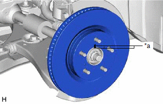
PROCEDURE 1. INSTALL FRONT DISC
2. INSTALL FRONT DISC BRAKE CYLINDER MOUNTING (a) Install the front disc brake cylinder mounting to the steering knuckle with the 2 bolts. Torque: 107 N·m {1091 kgf·cm, 79 ft·lbf} 3. INSTALL FRONT DISC BRAKE BUSHING DUST BOOT (a) Apply a light layer of lithium soap base glycol grease to the entire circumference of 2 new front disc brake bushing dust boots. HINT: Apply more than 0.3 g (0.01 oz) of lithium soap base glycol grease to each front disc brake bushing dust boot. 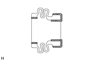
(b) Install the 2 front disc brake bushing dust boots to the front disc brake cylinder mounting. 4. INSTALL FRONT DISC BRAKE CYLINDER SLIDE PIN (a) Apply a light layer of lithium soap base glycol grease to the contact surface of the front disc brake cylinder slide pin (lower side). 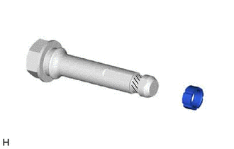
(b) Install a new front disc brake cylinder slide bushing to the front disc brake cylinder slide pin (lower side). (c) Apply a light layer of lithium soap base glycol grease to the sliding part and the sealing surfaces of the 2 front disc brake cylinder slide pins. 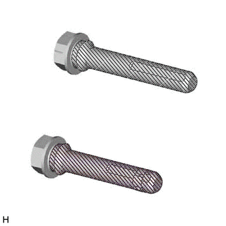
(d) Install the 2 front disc brake cylinder slide pins to the front disc brake cylinder mounting. (e) Push each front disc brake cylinder slide pin into the front disc brake bushing dust boot to engage the pin to the boot. 5. INSTALL FRONT DISC BRAKE PAD SUPPORT PLATE (a) Install the 4 front disc brake pad support plates to the front disc brake cylinder mounting. 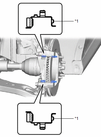
NOTICE: Install the 2 front disc brake pad support plates with the identification paint is mounted on the inner side of the vehicle. 6. INSTALL FRONT DISC BRAKE ANTI-SQUEAL SHIM KIT Click here
7. INSTALL FRONT DISC BRAKE PAD (a) Install the 2 front disc brake pads to the front disc brake cylinder mounting. NOTICE:
8. INSTALL FRONT DISC BRAKE CYLINDER ASSEMBLY (a) Apply disc brake grease to the contact surfaces of the front disc brake cylinder assembly and front disc brake pad as shown in the illustration. HINT: Apply 0.3 g (0.01 oz) of disc brake grease to the front disc brake cylinder assembly. 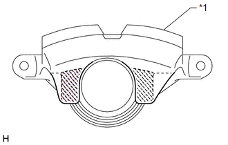
(b) Hold each front disc brake cylinder slide pin and install the front disc brake cylinder assembly to the front disc brake cylinder mounting with the 2 bolts. Torque: 34.3 N·m {350 kgf·cm, 25 ft·lbf} 9. CONNECT FRONT FLEXIBLE HOSE (a) Connect the front flexible hose to the front disc brake cylinder assembly with a new union bolt and a new gasket. Torque: 29.4 N·m {300 kgf·cm, 22 ft·lbf} NOTICE: Install the front flexible hose lock securely into the lock hole in the front disc brake cylinder assembly. 10. CONNECT CABLE TO NEGATIVE AUXILIARY BATTERY TERMINAL (for HV Model) (a) Connect the reservoir level switch connector. (b) Connect the cable to the negative (-) auxiliary battery terminal. Click here (c) Perform the following procedure if air bleeding is not necessary: (1) Turn the power switch on (READY). (2) Depress the brake pedal and release it. (3) Clear the DTCs. Click here 11. BLEED BRAKE LINE for Gasoline Model: Click here
for HV Model: Click here
12. INSTALL FRONT WHEEL Click here
|
Toyota Avalon (XX50) 2019-2022 Service & Repair Manual > Motor Generator Control System: Freeze Frame Data
FREEZE FRAME DATA FREEZE FRAME DATA HINT: The motor generator control ECU records vehicle and driving condition information as freeze frame data the moment a DTC is stored. It can be used for estimating or duplicating the vehicle conditions that were present when the malfunction occurred. (a) Connec ...