PARTS LOCATION ILLUSTRATION 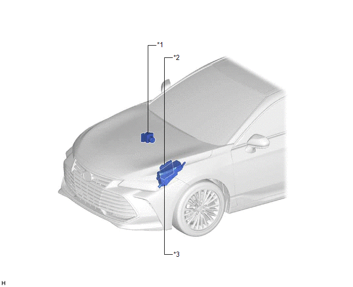
ILLUSTRATION 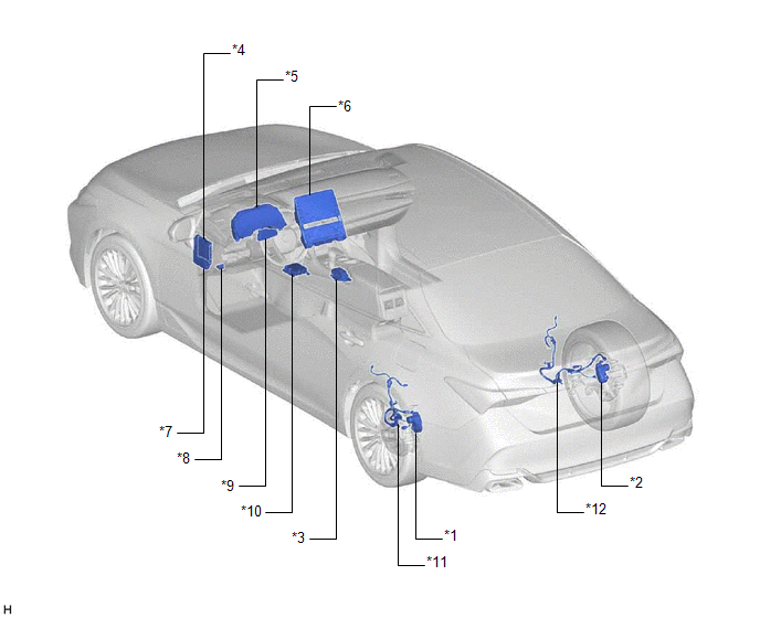
|
Toyota Avalon (XX50) 2019-2022 Service & Repair Manual > Power Mirror Control System(for Gasoline Model Without Memory): Precaution
PRECAUTION PRECAUTION FOR DISCONNECTING CABLE FROM NEGATIVE BATTERY TERMINAL NOTICE: When disconnecting the cable from the negative (-) battery terminal, initialize the following systems after the cable is reconnected. System Name See Procedure Lane Departure Alert System (w/ Steering Control) Intel ...


