REPLACEMENT CAUTION / NOTICE / HINT The necessary procedures (adjustment, calibration, initialization, or registration) that must be performed after parts are removed and installed, or replaced during front axle hub bolt removal/installation are shown below. Necessary Procedures After Parts Removed/Installed/Replaced (for HV Model:)
HINT:
PROCEDURE 1. PRECAUTION (for HV Model) NOTICE: After turning the power switch off, waiting time may be required before disconnecting the cable from the negative (-) auxiliary battery terminal. Therefore, make sure to read the disconnecting the cable from the negative (-) auxiliary battery terminal notices before proceeding with work. Click here 2. DISABLE BRAKE CONTROL (for HV Model) Click here 3. REMOVE FRONT WHEEL Click here 4. SEPARATE FRONT FLEXIBLE HOSE
5. SEPARATE FRONT DISC BRAKE CALIPER ASSEMBLY (a) Remove the 2 bolts and separate the front disc brake caliper assembly from the steering knuckle. NOTICE: Use wire or an equivalent tool to keep the front disc brake caliper assembly from hanging by the front flexible hose. 6. REMOVE FRONT DISC Click here 7. REMOVE FRONT AXLE HUB BOLT
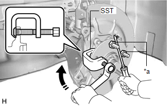
(b) Using SST and a screwdriver or an equivalent tool to hold the front axle hub sub-assembly, remove the front axle hub bolt. SST: 09611-12010 NOTICE: Do not damage the threads of the front axle hub bolts. 8. INSTALL FRONT AXLE HUB BOLT (a) Temporarily install a new front axle hub bolt to the front axle hub sub-assembly.
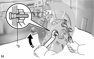
(c) Using a screwdriver or an equivalent tool to hold the front axle hub sub-assembly, install the front axle hub bolt by tightening the service nut. NOTICE:
(d) Remove the 3 service nuts and washer from the 3 front axle hub bolts. 9. INSTALL FRONT DISC Click here 10. INSTALL FRONT DISC BRAKE CALIPER ASSEMBLY (a) Install the front disc brake caliper assembly to the steering knuckle with the 2 bolts. Torque: 107 N·m {1091 kgf·cm, 79 ft·lbf} NOTICE:
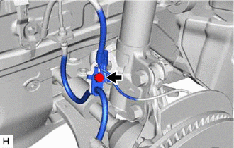
11. INSTALL FRONT FLEXIBLE HOSE (a) Engage the 2 hooks to install the front speed sensor clamp bracket. 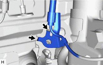
NOTICE: Do not twist the front speed sensor when installing it.
12. INSTALL FRONT WHEEL Click here 13. CONNECT CABLE TO NEGATIVE AUXILIARY BATTERY TERMINAL (for HV Model) (a) Connect the reservoir level switch connector. (b) Connect the cable to the negative (-) auxiliary battery terminal. Click here (c) Turn the power switch on (READY). (d) Depress the brake pedal and release it. (e) Clear the DTCs. Click here | ||||||||||||||||||||||||||||||||||||||||||
Toyota Avalon (XX50) 2019-2022 Service & Repair Manual > Transmission Control Cable: Installation
INSTALLATION PROCEDURE 1. INSTALL TRANSMISSION CONTROL CABLE ASSEMBLY (a) Turn the control shaft lever clockwise until it stops, then turn it counterclockwise 2 notches. (b) Engage the 2 claws to install a new clip to the transmission control cable assembly. (c) Using a screwdriver, engage the 4 cla ...