DISASSEMBLY CAUTION / NOTICE / HINT HINT:
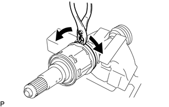
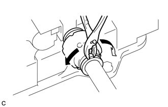
PROCEDURE 1. SEPARATE FRONT NO. 2 AXLE INBOARD JOINT BOOT CLAMP (a) Secure the drive shaft in a vise between aluminum plates. NOTICE: Do not overtighten the vise.
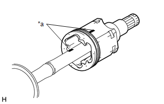
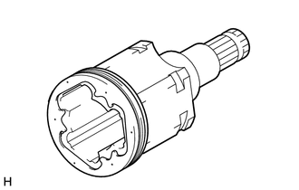
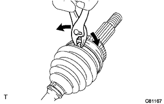
2. SEPARATE FRONT AXLE INBOARD JOINT BOOT CLAMP HINT: Perform the same procedure as for the front No. 2 axle inboard joint boot clamp. 3. SEPARATE FRONT AXLE INBOARD JOINT BOOT (a) Separate the front axle inboard joint boot from the front drive inboard joint assembly. 4. REMOVE FRONT DRIVE INBOARD JOINT ASSEMBLY (a) Remove the old grease from the front drive inboard joint assembly.
(c) Remove the front drive inboard joint assembly from the front drive outboard joint shaft assembly. (d) Secure the drive shaft in a vise between aluminum plates. NOTICE: Do not overtighten the vise.
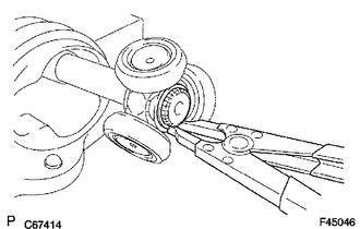
(g) Using a brass bar and a hammer, tap out the tripod joint from the front drive outboard joint shaft assembly. NOTICE:
5. REMOVE FRONT AXLE INBOARD JOINT BOOT (a) Remove the front No. 2 axle inboard joint boot clamp, front axle inboard joint boot and front axle inboard joint boot clamp. 6. REMOVE FRONT DRIVE SHAFT DAMPER CLAMP (for LH Side)
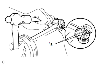
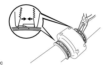
(b) Using pliers, separate the 2 front drive shaft damper clamps. 7. REMOVE FRONT DRIVE SHAFT DAMPER CLAMP (for RH Side) (a) Secure the drive shaft in a vise between aluminum plates. NOTICE: Do not overtighten the vise.
8. REMOVE FRONT DRIVE SHAFT DAMPER (a) Remove the front drive shaft damper and 2 front drive shaft damper clamps from the front drive outboard joint shaft assembly. 9. SEPARATE FRONT NO. 2 AXLE OUTBOARD JOINT BOOT CLAMP (a) Secure the drive shaft in a vise between aluminum plates. NOTICE: Do not overtighten the vise.
10. SEPARATE FRONT AXLE OUTBOARD JOINT BOOT CLAMP HINT: Perform the same procedure as for the front No. 2 axle outboard joint boot clamp. 11. REMOVE FRONT AXLE OUTBOARD JOINT BOOT (a) Remove the front axle outboard joint boot clamp, front axle outboard joint boot and front No. 2 axle outboard joint boot clamp from the front drive outboard joint shaft assembly. (b) Remove the old grease from the outboard joint. |
Toyota Avalon (XX50) 2019-2022 Service & Repair Manual > Meter / Gauge System(for Gasoline Model): Parts Location
PARTS LOCATION ILLUSTRATION *1 BRAKE FLUID LEVEL WARNING SWITCH (BRAKE MASTER CYLINDER RESERVOIR ASSEMBLY) *2 FUEL SENDER GAUGE ASSEMBLY *3 LEVEL WARNING SWITCH ASSEMBLY *4 POWER STEERING ECU (RACK AND PINION POWER STEERING GEAR ASSEMBLY) *5 SKID CONTROL ECU (BRAKE ACTUATOR ASSEMBLY) *6 VACUUM WARNI ...