DESCRIPTION Solenoid (SL)
valve is turned on and off by signals from the ECM to control the
hydraulic pressure acting on the lock-up relay valve, which then
controls operation of the lock-up clutch. |
DTC No. | Detection Item |
DTC Detection Condition | Trouble Area |
MIL | Memory |
Note | | P074011 |
Torque Converter Clutch Circuit Short to Ground |
While
the vehicle is being driven so that lock-up is not requested, a short
to ground is detected in the solenoid (SL) valve circuit (2-trip
detection logic). |
- Solenoid (SL) valve
- Transmission wire
- Harness and connector
- ECM
| Comes on |
DTC stored | SAE Code:
P2769 | Fail-safe function: If the ECM detects a malfunction, it turns Solenoid (SL) valve off. MONITOR DESCRIPTION
Based
on the signals from the throttle position sensor, the air flow meter
and the crankshaft position sensor, the ECM sends a signal to solenoid
(SL) valve to regulate the hydraulic pressure and provide smoother
torque converter engagement. Solenoid (SL) valve responds to commands
from the ECM. The valve controls the lock-up relay valve to perform the
torque-converter lock-up function. If the ECM detects a short to ground
in the solenoid (SL) valve circuit, it will illuminate the MIL and store
the DTC. MONITOR STRATEGY |
Related DTCs | P2769: Solenoid (SL) valve/Range check | |
Required sensors/components | Solenoid (SL) valve | |
Frequency of operation | Continuous | |
Duration | 1 time | |
MIL operation | 2 driving cycles | |
Sequence of operation | None | TYPICAL ENABLING CONDITIONS |
The monitor will run whenever the following DTCs are not stored |
None | | Battery voltage |
8 V or more | | Engine switch |
On (IG) | | Starter |
OFF | TYPICAL MALFUNCTION THRESHOLDS |
All of the following conditions are met |
0.065536 sec. or more | |
Time after command to solenoid OFF to ON |
0.008192 sec. or more | |
Command to solenoid | ON | |
Solenoid terminal voltage level | Low | COMPONENT OPERATING RANGE |
Solenoid (SL) valve | Resistance: 11 to 15 Ω at 20°C (68°F) | CONFIRMATION DRIVING PATTERN
CAUTION: When performing the confirmation driving pattern, obey all speed limits and traffic laws.
HINT:
- After repairs have been completed, clear the DTCs and then check that
the vehicle has returned to normal by performing the following All
Readiness check procedure.
- When clearing the permanent DTCs, refer to the Clear Permanent DTC procedure.
Click here 
- Connect the Techstream to the DLC3.
- Turn the engine switch on (IG) and turn the Techstream on.
- Clear the DTCs (even if no DTCs are stored, perform the clear DTC procedure).
- Turn the engine switch off and wait for 2 minutes or more.
- Turn the engine switch on (IG) and turn the Techstream on.
- Start the engine.
- Perform the Lock-up Function inspection in Road Test. [*1]
Click here
HINT:
[*1] : Normal judgment procedure.
The normal judgment procedure is used to complete DTC judgment and also used when clearing permanent DTCs.
- Stop the vehicle.
- Enter the following menus: Powertrain / Transmission / Utility / All Readiness.
- Input the DTC: P074011.
- Check the DTC judgment result.
|
Techstream Display |
Description |
|
NORMAL |
- DTC judgment completed
- System normal
|
|
ABNORMAL |
- DTC judgment completed
- System abnormal
|
|
INCOMPLETE |
- DTC judgment not completed
- Perform driving pattern after confirming DTC enabling conditions
|
|
N/A |
- Unable to perform DTC judgment
- Number of DTCs which do not fulfill DTC preconditions has reached ECU memory limit
|
HINT:
- If the judgment result shows NORMAL, the system is normal.
- If the judgment result shows ABNORMAL, the system has a malfunction.
- If the judgment result shows INCOMPLETE or N/A, perform the normal judgment procedure again.
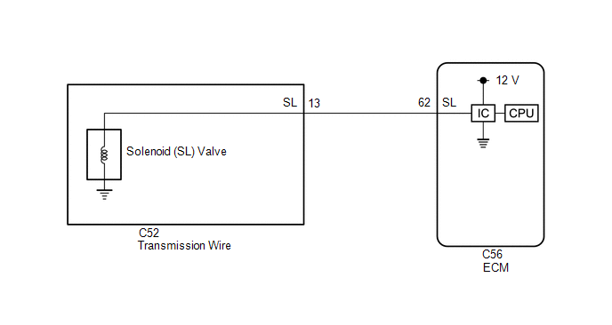
WIRING DIAGRAM
 CAUTION / NOTICE / HINT
NOTICE:
- Perform the universal trip to clear permanent DTCs.
Click here
- Perform registration and/or initialization when parts related to the automatic transaxle are replaced.
Click here
PROCEDURE |
1. | INSPECT TRANSMISSION WIRE (SOLENOID (SL) VALVE) |
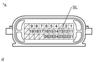
| (a) Disconnect the C52 transmission wire connector. |
 |
|
*a | Component without harness connected
(Transmission Wire) | | |
(b) Measure the resistance according to the value(s) in the table below.
Standard Resistance: |
Tester Connection | Condition |
Specified Condition | |
13 (SL) - Body ground |
20°C (68°F) | 11 to 15 Ω |
(c) Connect the C52 transmission wire connector.
| NG |
 | GO TO STEP 4 |
|
OK |
 | |
| 2. |
CHECK HARNESS AND CONNECTOR (TRANSMISSION WIRE - ECM) |
(a) Disconnect the C56 ECM connector. (b) Measure the resistance according to the value(s) in the table below.
Standard Resistance: |
Tester Connection | Condition |
Specified Condition | | C56-62 (SL) - Body ground |
20°C (68°F) | 11 to 15 Ω |
| NG |
| REPAIR OR REPLACE HARNESS OR CONNECTOR (TRANSMISSION WIRE - ECM) |
|
OK | |
| |
(a) Replace the ECM.
Click here
| NEXT |
| PERFORM REGISTRATION |
| 4. |
INSPECT SOLENOID (SL) VALVE |
| (a) Remove the solenoid (SL) valve. Click here
| |
(b) Measure the resistance according to the value(s) in the table below.
Standard Resistance: |
Tester Connection | Condition |
Specified Condition | |
Solenoid (SL) valve connector terminal - Solenoid (SL) valve body |
20°C (68°F) | 11 to 15 Ω |
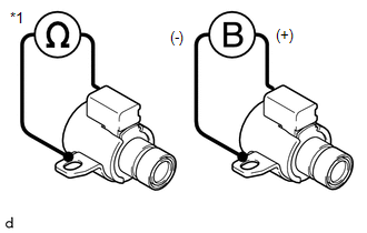
(c)
Connect a positive (+) lead from the battery to the terminal of the
solenoid valve connector, and a negative (-) lead to the solenoid body.
Check that the valve moves and makes an operating sound. OK: Valve moves and makes an operating sound.
| OK |
| REPAIR OR REPLACE TRANSMISSION WIRE |
| NG |
| REPLACE SOLENOID (SL) VALVE | |