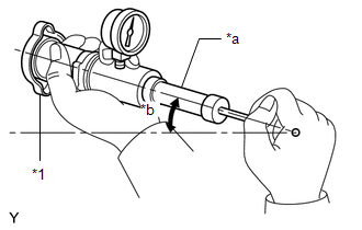
ON-VEHICLE INSPECTION CAUTION / NOTICE / HINT CAUTION: Do not remove the radiator cap sub-assembly while the engine and radiator assembly are still hot. Pressurized, hot engine coolant and steam may be released and cause serious burns. 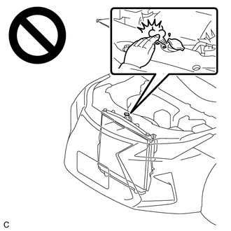 PROCEDURE 1. CHECK RADIATOR CAP SUB-ASSEMBLY CAUTION: Do not remove the radiator cap sub-assembly while the engine and radiator assembly are still hot. Pressurized, hot engine coolant and steam may be released and cause serious burns. (a) Measure the valve opening pressure. 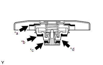
(1) If there are water stains or foreign matter on the rubber packing (1), (2) or (3), clean the part(s) with water and finger scouring. (2) Check that the rubber packings (1), (2) and (3) are not deformed, cracked or swollen. (3) Check that the rubber packing (3) and valve seat are not stuck together. (4) Apply engine coolant to the rubber packings (2) and (3) before using a radiator cap tester.
(6) Pump the radiator cap tester several times, and check the maximum pressure. Pumping Speed: 1 pump per second
HINT: Even if the radiator cap sub-assembly cannot maintain the maximum pressure, it is not a defect. If the maximum pressure is less than the minimum pressure, replace the radiator cap sub-assembly. 2. CHECK RADIATOR ASSEMBLY FOR CLOGGING CAUTION: To prevent burns, do not touch the engine or other high temperature components while the engine is hot. (a) Remove the cool air intake duct seal. Click here
(b) Remove the inlet air cleaner assembly. Click here (c) Shine an electric light at the radiator assembly and cooler condenser assembly from the front of the cooler condenser assembly and check the radiator assembly for clogging using a mirror. 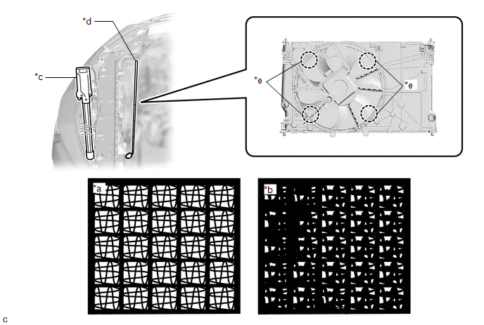
OK: The radiator assembly is not clogged. If the radiator assembly is clogged, clean it. (d) Install the inlet air cleaner assembly. Click here
(e) Install the cool air intake duct seal. Click here 3. CLEAN RADIATOR ASSEMBLY CAUTION: To prevent burns, do not touch the engine or other high temperature components while the engine is hot. (a) Remove the cool air intake duct seal. Click here
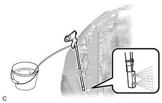
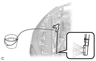
(b) Remove the inlet air cleaner assembly. Click here (c) Cover the opening of each air duct with a piece of cloth. (d) Clean the cooler condenser assembly. (1) Check that the washer nozzle is not clogged.
(3) Leave the cooler condenser assembly as is for 10 minutes to let the water penetrate the dirt. (4) Clean the cooler condenser assembly again. NOTICE:
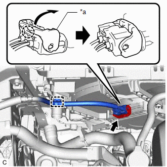
(5) Using an air blow gun, dry the cooler condenser assembly for 3 minutes. (e) Disconnect the cooling fan motor connector.
(2) Disengage the wire harness clamp.
(g) Clean the radiator assembly.
(2) Leave the radiator assembly as is for 10 minutes to let the water penetrate the dirt. (3) Clean the radiator assembly again. NOTICE:
(4) Using an air blow gun, dry the radiator assembly for 3 minutes. (h) Check the fins of the radiator assembly for clogs again. If the radiator assembly is clogged, clean the cooler condenser assembly and radiator assembly again.
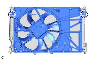
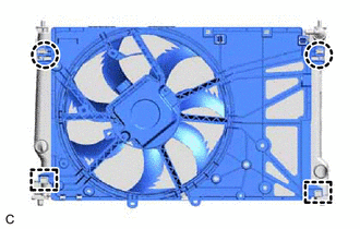
(j) Engage the 2 claws to install the fan with motor assembly to the radiator assembly. (k) Connect the cooling fan motor connector.
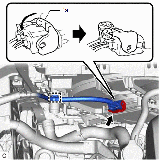
(2) Connect the cooling fan motor connector and push down the lock lever to engage the claw as shown in the illustration. NOTICE:
(l) Remove the piece of cloth from the opening of each air duct. (m) Install the inlet air cleaner assembly. Click here
(n) Install the cool air intake duct seal. Click here |
Toyota Avalon (XX50) 2019-2022 Service & Repair Manual > Electronically Controlled Brake System(for Hv Model): Servo Pressure Sensor Zero Point Malfunction (C14C3)
DESCRIPTION The Servo pressure sensor detects and outputs the brake fluid pressure generated in the wheel cylinder according to the vehicle condition to the skid control ECU (brake booster with master cylinder assembly). DTC No. Detection Item INF Code DTC Detection Condition Trouble Area MIL Note C ...