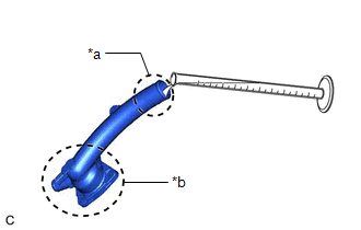
INSPECTION PROCEDURE 1. INSPECT WATER INLET WITH THERMOSTAT SUB-ASSEMBLY (a) Check the valve opening. HINT: The valve opening temperature is inscribed on the water inlet with thermostat sub-assembly. 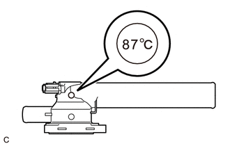
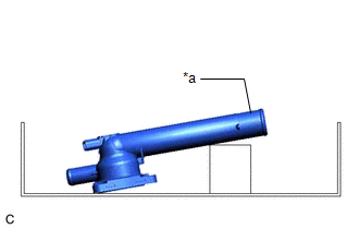
(2) Confirm that water does not flow out from the valve side of the water inlet with thermostat sub-assembly. If water flows out from the valve side of the water inlet with thermostat sub-assembly, replace the water inlet with thermostat sub-assembly with a new one. (3) Immerse the water inlet with thermostat sub-assembly in water that is between 92°C (198°F) and 96°C (205°F) for 5 minutes or more. NOTICE:
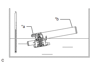
(5) Check that the water that was added to the water inlet with thermostat sub-assembly has completely flowed out. If the water that was added to the water inlet with thermostat sub-assembly has not completely flowed out, replace the water inlet with thermostat sub-assembly with a new one. (b) Check the resistance of the temperature sensor. (1) Measure the resistance according to the value(s) in the table below. Standard Resistance:
If the result is not as specified, replace the water inlet with thermostat sub-assembly. |
Toyota Avalon (XX50) 2019-2022 Service & Repair Manual > Side Turn Signal Light Assembly: Removal
REMOVAL CAUTION / NOTICE / HINT The necessary procedures (adjustment, calibration, initialization, or registration) that must be performed after parts are removed and installed, or replaced during side turn signal light assembly removal/installation are shown below. Necessary Procedure After Parts R ...