Components COMPONENTS ILLUSTRATION 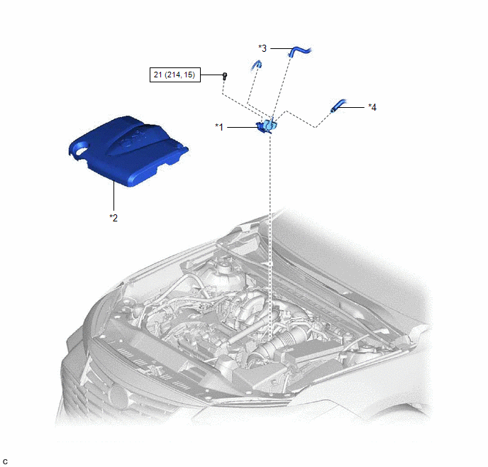
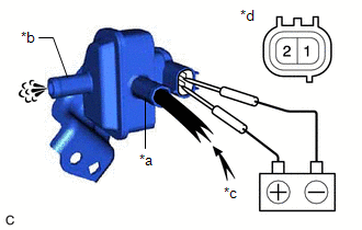
Inspection INSPECTION PROCEDURE 1. INSPECT PURGE VALVE (PURGE VSV) (a) Measure the resistance according to the value(s) in the table below. Standard Resistance:
If the result is not as specified, replace the purge valve (purge VSV).
Installation INSTALLATION PROCEDURE 1. INSTALL PURGE VALVE (PURGE VSV)
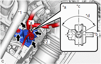
(b) Connect the No. 1 fuel vapor feed hose to the purge valve (purge VSV). (c) Connect the fuel vapor feed hose to the purge valve (purge VSV) and slide the clip to secure it. HINT: Engage the clip within the area shown in the illustration. (d) Connect the purge valve (purge VSV) connector. 2. INSTALL V-BANK COVER SUB-ASSEMBLY Click here Removal REMOVAL PROCEDURE 1. REMOVE V-BANK COVER SUB-ASSEMBLY Click here
2. REMOVE PURGE VALVE (PURGE VSV)
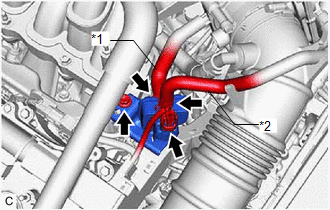
(b) Slide the clip and disconnect the fuel vapor feed hose from the purge valve (purge VSV). (c) Disconnect the No. 1 fuel vapor feed hose from the purge valve (purge VSV). (d) Remove the bolt and purge valve (purge VSV) from the intake air surge tank assembly. |
Toyota Avalon (XX50) 2019-2022 Service & Repair Manual > Suspension Control Ecu: Components
COMPONENTS ILLUSTRATION *1 BAGGAGE HOLDER NET *2 SPARE WHEEL COVER ASSEMBLY ILLUSTRATION *1 LUGGAGE COMPARTMENT INNER TRIM PAD *2 LUGGAGE COMPARTMENT TRIM INNER COVER RH *3 NO. 1 LUGGAGE COMPARTMENT TRIM HOOK *4 REAR FLOOR FINISH PLATE ILLUSTRATION *1 ABSORBER CONTROL ECU *2 CONNECTOR N*m (kgf*cm, f ...