DESCRIPTION Refer to DTC P011011. Click here
HINT: When DTC P011015 is stored, the ECM enters fail-safe mode. During fail-safe mode, the intake air temperature is estimated to be 20°C (68°F) by the ECM. Fail-safe mode continues until a pass condition is detected, and the engine switch is then turned off.
HINT: When this DTC is output, check the intake air temperature in the Data List. Enter the following menus: Powertrain / Engine / Data List / Intake Air Temperature.
If the Data List values is normal it may be due to a temporary recovery from the malfunction condition. Check for intermittent problems. MONITOR DESCRIPTION The ECM monitors the sensor voltage and uses this value to calculate the intake air temperature. When the intake air temperature sensor output voltage deviates from the normal operating range, the ECM interprets this as a malfunction in the intake air temperature sensor circuit and stores this DTC. Example: If the intake air temperature sensor output voltage is higher than 4.91 V for 0.5 seconds or more, the ECM store this DTC. MONITOR STRATEGY
TYPICAL ENABLING CONDITIONS
TYPICAL MALFUNCTION THRESHOLDS
CONFIRMATION DRIVING PATTERN HINT:
WIRING DIAGRAM Refer to DTC P010012. Click here
CAUTION / NOTICE / HINT HINT: Read freeze frame data using the Techstream. The ECM records vehicle and driving condition information as freeze frame data the moment a DTC is stored. When troubleshooting, freeze frame data can help determine if the vehicle was moving or stationary, if the engine was warmed up or not, if the air fuel ratio was lean or rich, and other data from the time the malfunction occurred. PROCEDURE
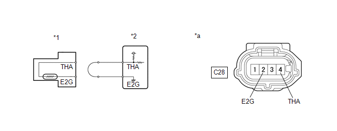
(a) Disconnect the mass air flow meter sub-assembly connector. (b) Connect terminals 4 (THA) and 2 (E2G) of the mass air flow meter sub-assembly connector on the wire harness side. (c) Connect the Techstream to the DLC3. (d) Turn the engine switch on (IG). (e) Turn the Techstream on. (f) Enter the following menus: Powertrain / Engine / Data List / Intake Air Temperature. Powertrain > Engine > Data List
(g) According to the display on the Techstream, read the Data List. OK:
HINT: Perform "Inspection After Repair" after replacing the mass air flow meter sub-assembly. Click here
(a) Disconnect the mass air flow meter sub-assembly connector. (b) Disconnect the ECM connector. (c) Measure the resistance according to the value(s) in the table below. Standard Resistance:
|
Toyota Avalon (XX50) 2019-2022 Service & Repair Manual > Safety Connect System(for Gasoline Model): Health Check
HEALTH CHECK HEALTH CHECK Health Check provides an overall view of vehicle status including telematics. Health Check will provide DCM (Telematics Transceiver) software version, PRL version, and applicable DTCs and fault codes related to telematics. (a) Connect the Techstream to the DLC3. (b) Turn th ...


