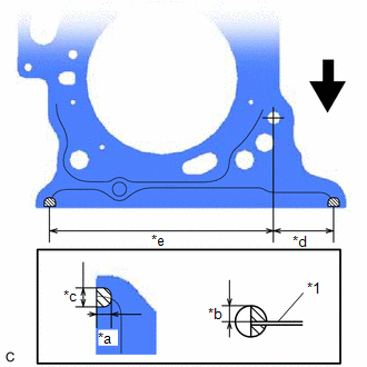
INSTALLATION PROCEDURE 1. INSTALL NO. 2 CYLINDER HEAD GASKET (a) Place a new No. 2 cylinder head gasket on the cylinder block sub-assembly as shown in the illustration. 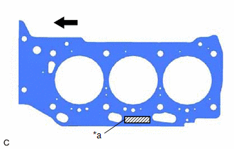
NOTICE:
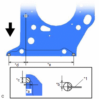
(b) Apply seal packing to the No. 2 cylinder head gasket as shown in the illustration. Seal Packing: Toyota Genuine Seal Packing Black, Three Bond 1207B or equivalent NOTICE:
2. INSTALL CYLINDER HEAD LH Click here 3. INSTALL CYLINDER HEAD GASKET (a) Place a new cylinder head gasket on the cylinder block sub-assembly as shown in the illustration. 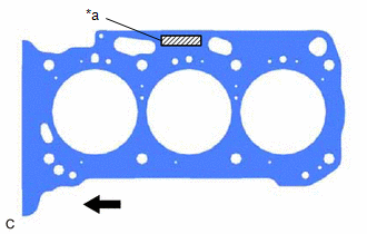
NOTICE:
(b) Apply seal packing to the cylinder head gasket as shown in the illustration. Seal Packing: Toyota Genuine Seal Packing Black, Three Bond 1207B or equivalent NOTICE:
4. INSTALL CYLINDER HEAD SUB-ASSEMBLY Click here 5. INSTALL WATER OUTLET Click here 6. INSTALL VALVE STEM CAP Click here 7. INSTALL VALVE LASH ADJUSTER ASSEMBLY Click here 8. INSTALL NO. 1 VALVE ROCKER ARM SUB-ASSEMBLY Click here 9. INSTALL NO. 1 CHAIN VIBRATION DAMPER Click here 10. INSTALL NO. 2 CHAIN VIBRATION DAMPER Click here 11. INSTALL SENSOR WIRE Click here 12. INSTALL NO. 3 CAMSHAFT SUB-ASSEMBLY Click here 13. INSTALL NO. 4 CAMSHAFT SUB-ASSEMBLY Click here 14. INSTALL CAMSHAFT BEARING CAP (for Bank 2) Click here 15. SET CAMSHAFT TIMING GEAR ASSEMBLY, CAMSHAFT TIMING EXHAUST GEAR ASSEMBLY AND NO. 2 CHAIN SUB-ASSEMBLY (for Bank 2) Click here 16. TEMPORARILY INSTALL CAMSHAFT TIMING GEAR BOLT (for Intake Side of Bank 2) Click here 17. TEMPORARILY INSTALL CAMSHAFT TIMING GEAR BOLT (for Exhaust Side of Bank 2) Click here 18. INSTALL CAMSHAFT HOUSING SUB-ASSEMBLY LH Click here 19. TIGHTEN CAMSHAFT TIMING GEAR BOLT (for Intake Side of Bank 2) Click here 20. TIGHTEN CAMSHAFT TIMING GEAR BOLT (for Exhaust Side of Bank 2) Click here 21. INSTALL CAMSHAFT Click here 22. INSTALL NO. 2 CAMSHAFT Click here 23. INSTALL CAMSHAFT BEARING CAP (for Bank 1) Click here 24. SET CAMSHAFT TIMING GEAR ASSEMBLY, CAMSHAFT TIMING EXHAUST GEAR ASSEMBLY AND NO. 2 CHAIN SUB-ASSEMBLY (for Bank 1) Click here 25. TEMPORARILY INSTALL CAMSHAFT TIMING GEAR BOLT (for Intake Side of Bank 1) Click here 26. TEMPORARILY INSTALL CAMSHAFT TIMING GEAR BOLT (for Exhaust Side of Bank 1) Click here 27. INSTALL CAMSHAFT HOUSING SUB-ASSEMBLY Click here 28. TIGHTEN CAMSHAFT TIMING GEAR BOLT (for Intake Side of Bank 1) Click here 29. TIGHTEN CAMSHAFT TIMING GEAR BOLT (for Exhaust Side of Bank 1) Click here 30. INSTALL NO. 3 CHAIN TENSIONER ASSEMBLY Click here 31. INSTALL NO. 2 CHAIN TENSIONER ASSEMBLY Click here 32. INSTALL CHAIN SUB-ASSEMBLY Click here 33. INSTALL CHAIN TENSIONER SLIPPER Click here 34. INSTALL NO. 1 CHAIN TENSIONER ASSEMBLY Click here 35. INSPECT VALVE TIMING Click here 36. INSTALL TIMING CHAIN COVER ASSEMBLY Click here 37. INSTALL TIMING CHAIN CASE OIL SEAL Click here 38. INSTALL OIL PAN SUB-ASSEMBLY (a) Install 2 new oil pan gaskets to the timing chain cover assembly.
(c) Install the oil pan sub-assembly with the 16 bolts and 2 nuts in the order shown in the illustration. 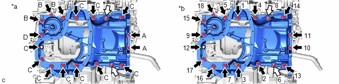
Torque: Bolt (A) : 10 N·m {102 kgf·cm, 7 ft·lbf} Bolt (B), (C), (D) : 21 N·m {214 kgf·cm, 15 ft·lbf} Nut : 21 N·m {214 kgf·cm, 15 ft·lbf} Bolt Length:
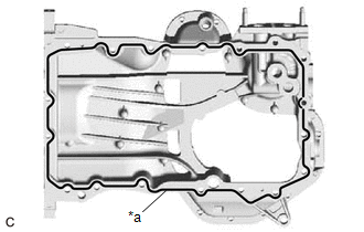
(d) Wipe off any excess seal packing with a clean piece of cloth. NOTICE: Do not allow seal packing to contact the No. 1 crankshaft position sensor plate. 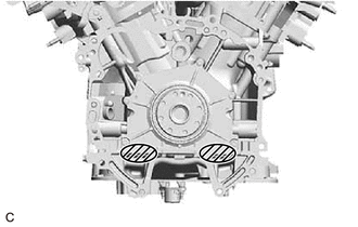
39. INSTALL OIL STRAINER SUB-ASSEMBLY Click here 40. INSTALL NO. 2 OIL PAN SUB-ASSEMBLY Click here 41. INSTALL SPARK PLUG TUBE GASKET Click here 42. INSTALL CYLINDER HEAD COVER SUB-ASSEMBLY LH Click here 43. INSTALL CYLINDER HEAD COVER SUB-ASSEMBLY Click here 44. INSTALL SENSOR WIRE Click here 45. INSTALL CRANKSHAFT POSITION SENSOR PROTECTOR Click here 46. INSTALL CAMSHAFT TIMING OIL CONTROL SOLENOID ASSEMBLY (for Intake Side of Bank 2) Click here 47. INSTALL CAMSHAFT TIMING OIL CONTROL SOLENOID ASSEMBLY (for Exhaust Side of Bank 2) Click here 48. INSTALL CAMSHAFT TIMING OIL CONTROL SOLENOID ASSEMBLY (for Exhaust Side of Bank 1) Click here 49. INSTALL CAMSHAFT TIMING OIL CONTROL SOLENOID ASSEMBLY (for Intake Side of Bank 1) Click here 50. INSTALL WATER INLET WITH THERMOSTAT SUB-ASSEMBLY Click here 51. CONNECT WATER BY-PASS HOSE Click here 52. INSTALL FRONT NO. 1 ENGINE MOUNTING BRACKET LH Click here 53. INSTALL CRANKSHAFT PULLEY Click here 54. INSTALL WATER FILLER BRACKET Click here 55. INSTALL WIRE HARNESS CLAMP BRACKET Click here 56. INSTALL ENGINE OIL LEVEL DIPSTICK GUIDE Click here 57. INSTALL WATER PUMP PULLEY Click here 58. INSTALL V-RIBBED BELT TENSIONER ASSEMBLY Click here 59. INSTALL NO. 2 IDLER PULLEY SUB-ASSEMBLY Click here 60. INSTALL COMPRESSOR ASSEMBLY WITH MAGNETIC CLUTCH Click here 61. INSTALL GENERATOR ASSEMBLY Click here 62. INSTALL V-RIBBED BELT Click here 63. INSTALL VACUUM PUMP ASSEMBLY Click here 64. INSTALL IGNITION COIL ASSEMBLY Click here 65. INSTALL KNOCK CONTROL SENSOR Click here 66. INSTALL ENGINE HANGERS Click here 67. REMOVE ENGINE ASSEMBLY FROM ENGINE STAND Click here |
Toyota Avalon (XX50) 2019-2022 Service & Repair Manual > Lighting System(for Hv Model Without Cornering Light): Daytime Running Light Circuit
DESCRIPTION The main body ECU (multiplex network body ECU) controls the daytime running lights. WIRING DIAGRAM CAUTION / NOTICE / HINT NOTICE: Inspect the fuses for circuits related to this system before performing the following procedure. Before replacing the main body ECU (multiplex network body E ...