REMOVAL CAUTION / NOTICE / HINT The necessary procedures (adjustment, calibration, initialization or registration) that must be performed after parts are removed and installed, or replaced during cylinder head gasket removal/installation are shown below. Necessary Procedure After Parts Removed/Installed/Replaced
PROCEDURE 1. INSTALL ENGINE ASSEMBLY TO ENGINE STAND Click here 2. REMOVE ENGINE HANGERS Click here 3. REMOVE KNOCK CONTROL SENSOR Click here 4. REMOVE IGNITION COIL ASSEMBLY Click here 5. REMOVE VACUUM PUMP ASSEMBLY Click here 6. REMOVE V-RIBBED BELT Click here 7. REMOVE GENERATOR ASSEMBLY Click here 8. REMOVE COMPRESSOR ASSEMBLY WITH MAGNETIC CLUTCH Click here 9. REMOVE NO. 2 IDLER PULLEY SUB-ASSEMBLY Click here 10. REMOVE V-RIBBED BELT TENSIONER ASSEMBLY Click here 11. REMOVE WATER PUMP PULLEY Click here 12. REMOVE ENGINE OIL LEVEL DIPSTICK GUIDE Click here 13. REMOVE WIRE HARNESS CLAMP BRACKET Click here 14. REMOVE WATER FILLER BRACKET Click here 15. REMOVE CRANKSHAFT PULLEY Click here 16. REMOVE FRONT NO. 1 ENGINE MOUNTING BRACKET LH Click here 17. DISCONNECT WATER BY-PASS HOSE Click here 18. REMOVE WATER INLET WITH THERMOSTAT SUB-ASSEMBLY Click here 19. REMOVE CAMSHAFT TIMING OIL CONTROL SOLENOID ASSEMBLY (for Intake Side of Bank 1) Click here 20. REMOVE CAMSHAFT TIMING OIL CONTROL SOLENOID ASSEMBLY (for Exhaust Side of Bank 1) Click here 21. REMOVE CAMSHAFT TIMING OIL CONTROL SOLENOID ASSEMBLY (for Exhaust Side of Bank 2) Click here 22. REMOVE CAMSHAFT TIMING OIL CONTROL SOLENOID ASSEMBLY (for Intake Side of Bank 2) Click here 23. REMOVE VVT SENSOR (for Intake Side of Bank 1) Click here 24. REMOVE VVT SENSOR (for Exhaust Side of Bank 1) Click here 25. REMOVE VVT SENSOR (for Intake Side of Bank 2) Click here 26. REMOVE VVT SENSOR (for Exhaust Side of Bank 2) Click here 27. REMOVE CRANKSHAFT POSITION SENSOR PROTECTOR Click here 28. REMOVE SENSOR WIRE Click here 29. REMOVE CYLINDER HEAD COVER SUB-ASSEMBLY Click here 30. REMOVE CYLINDER HEAD COVER SUB-ASSEMBLY LH Click here 31. REMOVE SPARK PLUG TUBE GASKET Click here 32. REMOVE NO. 2 OIL PAN SUB-ASSEMBLY Click here 33. REMOVE OIL STRAINER SUB-ASSEMBLY Click here 34. REMOVE OIL PAN SUB-ASSEMBLY
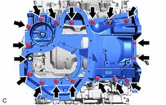
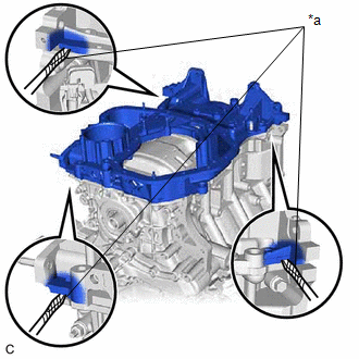
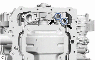
35. REMOVE TIMING CHAIN COVER ASSEMBLY Click here
36. REMOVE TIMING GEAR CASE OR TIMING CHAIN CASE OIL SEAL Click here 37. SET NO. 1 CYLINDER TO TDC (COMPRESSION) Click here 38. REMOVE NO. 1 CHAIN TENSIONER ASSEMBLY Click here 39. REMOVE CHAIN TENSIONER SLIPPER Click here 40. REMOVE CHAIN SUB-ASSEMBLY Click here 41. REMOVE CAMSHAFT TIMING GEAR ASSEMBLY, CAMSHAFT TIMING EXHAUST GEAR ASSEMBLY AND NO. 2 CHAIN SUB-ASSEMBLY (for Bank 1) Click here 42. REMOVE NO. 2 CHAIN TENSIONER ASSEMBLY Click here 43. REMOVE CAMSHAFT BEARING CAP (for Bank 1) Click here 44. REMOVE CAMSHAFT Click here 45. REMOVE NO. 2 CAMSHAFT Click here 46. REMOVE CAMSHAFT HOUSING SUB-ASSEMBLY Click here 47. REMOVE CAMSHAFT TIMING GEAR ASSEMBLY, CAMSHAFT TIMING EXHAUST GEAR ASSEMBLY AND NO. 2 CHAIN SUB-ASSEMBLY (for Bank 2) Click here 48. REMOVE NO. 3 CHAIN TENSIONER ASSEMBLY Click here 49. REMOVE CAMSHAFT BEARING CAP (for Bank 2) Click here 50. REMOVE NO. 3 CAMSHAFT SUB-ASSEMBLY Click here 51. REMOVE NO. 4 CAMSHAFT SUB-ASSEMBLY Click here 52. REMOVE CAMSHAFT HOUSING SUB-ASSEMBLY LH Click here 53. REMOVE SENSOR WIRE Click here 54. REMOVE NO. 1 CHAIN VIBRATION DAMPER Click here 55. REMOVE NO. 2 CHAIN VIBRATION DAMPER Click here 56. REMOVE NO. 1 VALVE ROCKER ARM SUB-ASSEMBLY Click here 57. REMOVE VALVE LASH ADJUSTER ASSEMBLY Click here 58. REMOVE VALVE STEM CAP Click here 59. REMOVE WATER OUTLET Click here 60. REMOVE CYLINDER HEAD SUB-ASSEMBLY Click here 61. REMOVE CYLINDER HEAD GASKET (a) Remove the cylinder head gasket from the cylinder block sub-assembly. 62. REMOVE CYLINDER HEAD LH Click here 63. REMOVE NO. 2 CYLINDER HEAD GASKET (a) Remove the No. 2 cylinder head gasket from the cylinder block sub-assembly. 64. INSPECT CYLINDER HEAD SET BOLT Click here
|
Toyota Avalon (XX50) 2019-2022 Service & Repair Manual > Sfi System: Fuel Pump Control (All Phase) Circuit Open (P12D013-P12D313)
DESCRIPTION Refer to DTC P062712. Click here DTC No. Detection Item DTC Detection Condition Trouble Area MIL Memory Note P12D013 Fuel Pump Control (All Phase) Circuit Open When the fuel pump control ECU operation duty ratio is 3 to 65%, an open is detected in the FPU, FPV and FPW circuit for 3 secon ...