REMOVAL CAUTION / NOTICE / HINT The necessary procedures (adjustment, calibration, initialization or registration) that must be performed after parts are removed and installed, or replaced during intake manifold removal/installation are shown below. Necessary Procedures After Parts Removed/Installed/Replaced
PROCEDURE 1. PRECAUTION NOTICE: After turning the engine switch off, waiting time may be required before disconnecting the cable from the negative (-) battery terminal. Therefore, make sure to read the disconnecting the cable from the negative (-) battery terminal notices before proceeding with work. Click here
2. DISCHARGE FUEL SYSTEM PRESSURE Click here 3. DISCONNECT CABLE FROM NEGATIVE BATTERY TERMINAL NOTICE: When disconnecting the cable, some systems need to be initialized after the cable is reconnected. Click here 4. REMOVE COWL TOP VENTILATOR LOUVER SUB-ASSEMBLY Click here 5. REMOVE FRONT CENTER UPPER SUSPENSION BRACE SUB-ASSEMBLY Click here 6. REMOVE THROTTLE BODY WITH MOTOR ASSEMBLY Click here 7. REMOVE V-BANK COVER SUB-ASSEMBLY Click here 8. DISCONNECT VENTILATION HOSE
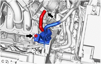
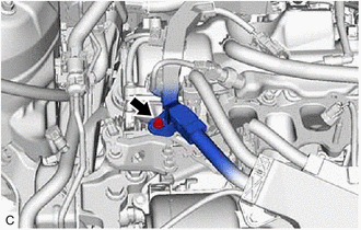
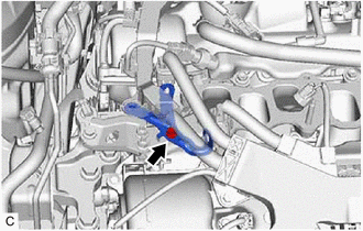
9. DISCONNECT PURGE VALVE (PURGE VSV)
(b) Remove the bolt and disconnect the purge valve (purge VSV) from the intake air surge tank assembly. 10. REMOVE NO. 2 SURGE TANK STAY
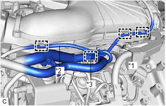
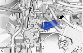
11. REMOVE INTAKE AIR SURGE TANK ASSEMBLY
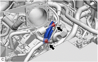
(b) Disengage the 2 clamps to disconnect the vacuum hose sub-assembly from the intake air surge tank assembly.
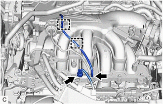
(d) Disengage the clamp to disconnect the vacuum hose from the intake air surge tank assembly. (e) Disengage the clamp to disconnect the No. 2 air tube from the intake air surge tank assembly. (f) Remove the 5 bolts, 2 nuts and intake air surge tank assembly from the intake manifold. 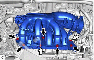
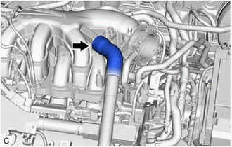
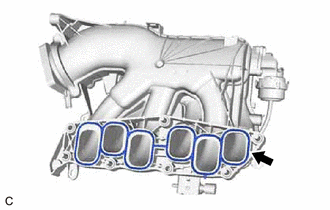
(g) Remove the plug from the intake air surge tank assembly. 12. REMOVE AIR SURGE TANK TO INTAKE MANIFOLD GASKET
13. REMOVE NO. 1 V-BANK COVER BRACKET HINT: Perform this procedure only when replacement of the No. 1 V-bank cover bracket is necessary.
14. REMOVE NO. 2 ENGINE MOUNTING STAY RH
(c) Remove the bolt, 2 nuts and No. 2 engine mounting stay RH from the engine mounting insulator sub-assembly RH. 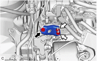
15. DISCONNECT FUEL TUBE SUB-ASSEMBLY Click here
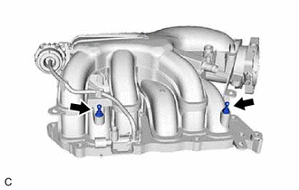
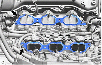
16. REMOVE FUEL DELIVERY PIPE WITH SENSOR ASSEMBLY Click here 17. REMOVE NO. 1 DELIVERY PIPE SPACER Click here 18. REMOVE INJECTOR VIBRATION INSULATOR Click here 19. REMOVE INTAKE MANIFOLD (a) Remove the 4 bolts, 4 nuts and intake manifold from the cylinder head sub-assembly. 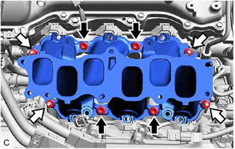
20. REMOVE NO. 1 INTAKE MANIFOLD TO HEAD GASKET
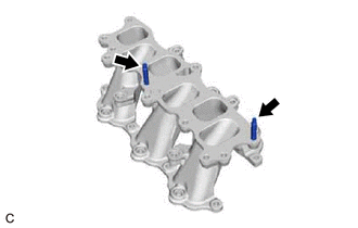
21. REMOVE STUD BOLT HINT: If a stud bolt is deformed or the threads are damaged, replace it.
| |||||||||||||||||||||||||||||||||||||||||||||||||||||||||||||||||||||||||||||||
Toyota Avalon (XX50) 2019-2022 Service & Repair Manual > Pre-collision System(for Hv Model): Brake Control Signal Mismatch (C1A64)
DESCRIPTION The skid control ECU (brake booster with master cylinder assembly) sends signals to the driving support ECU assembly according to the brake control status. If the driving support ECU assembly receives an electronically controlled brake system malfunction signal from the skid control ECU ...