INSTALLATION PROCEDURE 1. INSTALL FLOW SHUTTING VALVE (WATER BY-PASS HOSE ASSEMBLY)
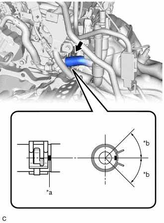
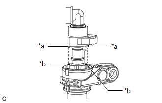
(b) Connect the flow shutting valve (water by-pass hose assembly) with the bolt. Torque: 19 N·m {194 kgf·cm, 14 ft·lbf} (c) Connect the No. 2 water by-pass pipe sub-assembly with the bolt. Torque: 19 N·m {194 kgf·cm, 14 ft·lbf} (d) Connect the inlet heater hose connector to the flow shutting valve (water by-pass hose assembly). NOTICE: Check that there is no damage or foreign matter on the connecting parts of the water lines.
(2) Push in the retainer. 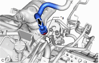
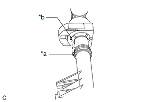
(3) Check that the flow shutting valve (water by-pass hose assembly) and inlet heater hose connector are securely connected by pulling on them. (e) Connect the outlet heater hose connector to the No. 2 water by-pass pipe sub-assembly. NOTICE: Check that there is no damage or foreign matter on the connecting parts of the water lines.
(2) Push in the retainer. 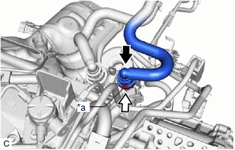
(3) Check that the No. 2 water by-pass pipe sub-assembly and outlet heater hose connector are securely connected by pulling on them. (f) Connect the flow shutting valve (water by-pass hose assembly) connector. 2. INSTALL INVERTER WITH CONVERTER ASSEMBLY Click here
3. ADD ENGINE COOLANT (for Engine) Click here 4. INSPECT FOR COOLANT LEAK (for Engine) Click here |
Toyota Avalon (XX50) 2019-2022 Service & Repair Manual > Can Communication System(for Hv Model): ECU Malfunction (B1003)
DESCRIPTION DTC No. Detection Item DTC Detection Condition Trouble Area Note B1003 ECU Malfunction A malfunction in the non-volatile storage of the central gateway ECU (network gateway ECU) is detected. Central gateway ECU (network gateway ECU) - PROCEDURE 1. RECONFIRM DTC OUTPUT (a) Connect the Tec ...