REMOVAL CAUTION / NOTICE / HINT The necessary procedures (adjustment, calibration, initialization, or registration) that must be performed after parts are removed and installed, or replaced during flow shutting valve (water by-pass hose assembly) removal/installation are shown below. Necessary Procedures After Parts Removed/Installed/Replaced
NOTICE: After turning the power switch off, waiting time may be required before disconnecting the cable from the negative (-) auxiliary battery terminal. Therefore, make sure to read the disconnecting the cable from the negative (-) auxiliary battery terminal notices before proceeding with work. Click here PROCEDURE 1. REMOVE INVERTER WITH CONVERTER ASSEMBLY Click here
2. DRAIN ENGINE COOLANT (for Engine) Click here 3. REMOVE FLOW SHUTTING VALVE (WATER BY-PASS HOSE ASSEMBLY)
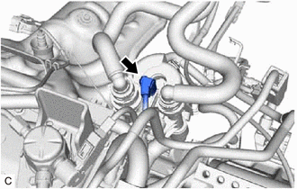
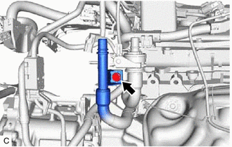
(b) Disconnect the outlet heater hose connector from the No. 2 water by-pass pipe sub-assembly. NOTICE: Remove any foreign matter on the No. 2 water by-pass pipe sub-assembly and outlet heater hose connector before performing this work. (1) Pull out the retainer to disengage the lock claws and pull off the outlet heater hose connector. 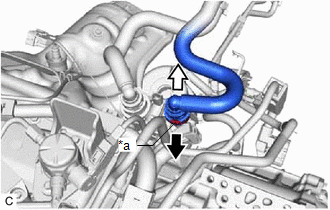
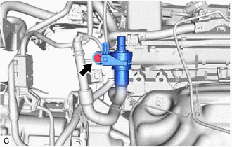
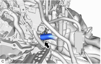
(2) Check that there is no foreign matter on the sealing surfaces of the disconnected water lines. Clean them if necessary. (3) Cover the disconnected No. 2 water by-pass pipe sub-assembly and outlet heater hose connector with plastic bags to prevent damage and contamination. (c) Disconnect the inlet heater hose connector from the flow shutting valve (water by-pass hose assembly). NOTICE: Remove any foreign matter on the flow shutting valve (water by-pass hose assembly) and inlet heater hose connector before performing this work. (1) Pull out the retainer to disengage the lock claws and pull off the inlet heater hose connector. 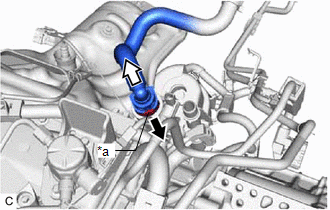
(2) Check that there is no foreign matter on the sealing surfaces of the disconnected water lines. Clean them if necessary. (3) Cover the disconnected inlet heater hose connector with plastic bag to prevent damage and contamination.
| ||||||||||||||||||||||||||||||||||||||||||||||||||||
Toyota Avalon (XX50) 2019-2022 Service & Repair Manual > Hybrid Control System: High Voltage Power Resource Circuit Voltage Sensor after Boosting Malfunction (P1C8349)
DTC SUMMARY MALFUNCTION DESCRIPTION The hybrid vehicle control ECU monitors the high-voltage wiring between the HV battery and inverter with converter assembly and detects a power supply malfunction. The cause of this malfunction may be one of the following: Inverter voltage sensor (VH) internal cir ...