DESCRIPTION The idle speed
is controlled by the electronic throttle control system. The electronic
throttle control system is comprised of: 1) one valve type throttle body
with motor assembly; 2) the throttle actuator, which operates the
throttle valve; 3) the throttle position sensor, which detects the
opening angle of the throttle valve; 4) the accelerator pedal position
sensor, which detects the accelerator pedal position; 5) the ECM, which
controls the electronic throttle control system. Based on the target
idle speed, the ECM controls the throttle actuator to provide the proper
throttle valve opening angle. |
DTC No. | Detection Item |
DTC Detection Condition | Trouble Area |
MIL | Memory |
Note | | P050500 |
Idle Control System | The idle speed differs largely from the target idle speed (2 trip detection logic). |
- Electronic throttle control system
- Intake system
- PCV hose connection
- EGR valve assembly
- ECM
| Comes on |
DTC stored | SAE Code: P0505 | MONITOR DESCRIPTION
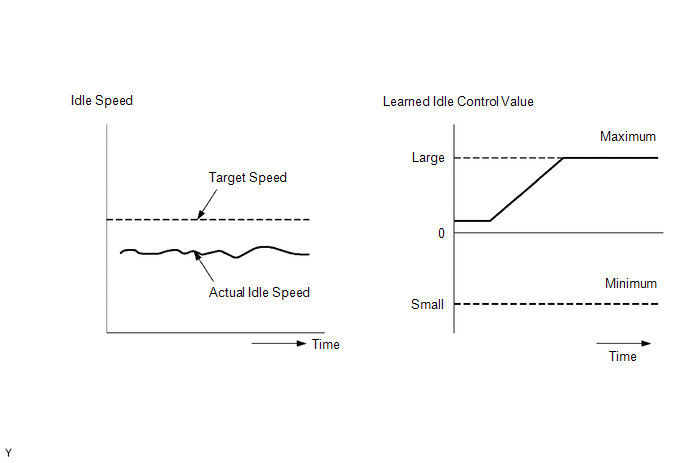
The
ECM monitors the idle speed and idling air flow volume to conduct idle
speed control. The ECM determines that the idle speed control system is
malfunctioning if either of the following conditions is met:
- The difference between the target engine idle speed and actual engine
idle speed exceeds the threshold and the idle control correction value
is stuck at the upper or lower limit for 5 seconds or more.
- After driving at a vehicle speed of 10 km/h (6 mph) or more, the
difference between the target and actual engine idle speed exceeds the
threshold 5 times or more during a driving cycle, and then the system
determines that the idle control correction value is stuck at the upper
or lower limit, or that the idle control correction value has been
changed by an amount that exceeds the threshold.
MONITOR STRATEGY |
Related DTCs | P0505: Idle speed control system functional check | |
Required Sensors/Components (Main) | Electronic throttle control system | |
Required Sensors/Components (Related) |
Crankshaft position sensor Engine coolant temperature sensor
Vehicle speed sensor | | Frequency of Operation |
Continuous | | Duration |
5 seconds | | MIL Operation |
2 driving cycles | | Sequence of Operation |
None | TYPICAL ENABLING CONDITIONS |
Monitor runs whenever the following DTCs are not stored |
P0010, P1360, P1362, P1364, P1366, P2614 (Motor drive VVT system control module)
P0011 (VVT system - advance) P0012 (VVT system - retard) P0013 (Exhaust VVT oil control solenoid)
P0014 (Exhaust VVT system - advance) P0015 (Exhaust VVT system - retard)
P0016 (VVT system - misalignment) P0017 (Exhaust VVT system - misalignment)
P0031, P0032, P101D (Air fuel ratio sensor (sensor 1) heater) P0101, P0102, P0103 (Mass air flow meter)
P0107, P0108 (Manifold absolute pressure) P0116, P0117, P0118 (Engine coolant temperature sensor)
P0121, P0122, P0123, P0222, P0223, P2135 (Throttle position sensor)
P0125 (Insufficient coolant temperature for closed loop fuel control)
P014C, P014D, P015A, P015B, P2195, P2196, P2237, P2238, P2239, P2252, P2253 (Air fuel ratio sensor (sensor 1))
P0171, P0172 (Fuel system) P0300, P0301, P0302, P0303, P0304 (Misfire)
P0335, P0337, P0338 (Crankshaft position sensor) P0340, P0342, P0343 (Camshaft position sensor)
P0365, P0367, P0368 (Exhaust camshaft position sensor) P0401 (EGR system (closed))
P0657, P0658, P2102, P2103, P2111, P2112, P2119 (Throttle actuator)
P11EA, P11EC, P11ED, P11EE, P11EF, P219A, P219C, P219D, P219E, P219F (Air-fuel ratio imbalance)
P1452, P1453 (EVAP system) P2228, P2229 (Atmospheric pressure sensor) | |
Engine | Running | TYPICAL MALFUNCTION THRESHOLDS |
Either of the following conditions is met |
1 or 2 | | 1. Both of the following conditions A and B met |
- | | A. Engine speed - Target engine speed |
Less than -100 rpm, or higher than 150 rpm | |
B. Idle control correction value | -7 Nm or less, or 15 Nm or more for 5 seconds or more | |
2. Both of the following conditions C and D met |
- | | C. Frequency that all of following conditions (a), (b) and (c) met |
5 times or more | | (a) Engine speed - Target engine speed |
Less than -100 rpm, or higher than 150 rpm | |
(b) Idle control learning value (value when last idle) |
-5 Nm or less, or 10 Nm or more | |
(c) Vehicle condition | Stopped after being driven at 10 km/h (6.25 mph) or more | |
D. Amount of change Idle control correction value |
-12.09 Nm or less, or 7.16 Nm or more | CONFIRMATION DRIVING PATTERN
HINT:
- After repair has been completed, clear the DTC and then check that the
vehicle has returned to normal by performing the following All Readiness
check procedure.
Click here 
- When clearing the permanent DTCs, refer to the "CLEAR PERMANENT DTC" procedure.
Click here
- Connect the Techstream to the DLC3.
- Turn the power switch on (IG).
- Turn the Techstream on.
- Clear the DTCs (even if no DTCs are stored, perform the clear DTC procedure).
- Turn the power switch off and wait for at least 30 seconds.
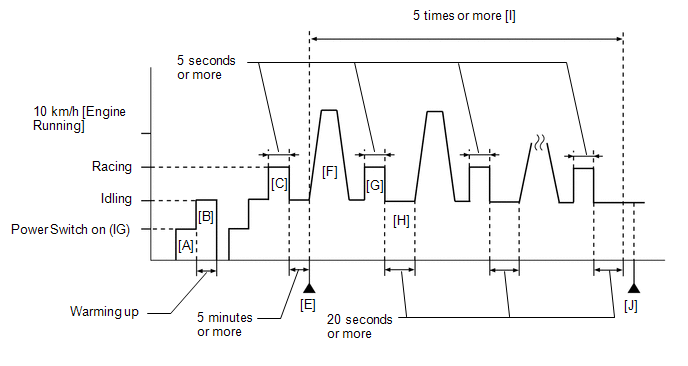
- Turn the power switch on (IG) [A].
- Turn the Techstream on.
- Put the engine in Inspection Mode (Maintenance Mode).
Click here
- Start the engine and warm it up until the engine coolant temperature is
75°C (167°F) or higher with the A/C switch and all the accessories off
[B].
- Turn the power switch off and wait for at least 30 seconds.
- Disconnect the cable from the negative (-) auxiliary battery terminal.
HINT:
When clearing permanent DTCs, proceed to the next step without disconnecting the cable from the auxiliary battery terminal.
- Reconnect the cable to the negative (-) auxiliary battery terminal.
- Turn the power switch on (IG).
- Turn the Techstream on.
- Put the engine in Inspection Mode (Maintenance Mode).
Click here
- Start the engine and rev the engine for 5 seconds or more with the shift lever in P [C].
HINT:
During
charge control, the engine speed is set at idle. Therefore, the engine
speed will not increase when the accelerator pedal is depressed. In this
case, perform step [C] after charge control has completed.
- Idle the engine for 5 minutes or more [D].
HINT:
In order to keep the idling stable, turn off the A/C and all other electric loads and do not perform any shift operations.
- Enter the following menus: Powertrain / Engine / Trouble Codes [E].
- Read the pending DTCs.
HINT:
- If a pending DTC is output, the system is malfunctioning.
- If a pending DTC is not output, perform the following procedure.
- Enter the following menus: Powertrain / Engine / Utility / All Readiness.
- Input the DTC: P050500.
- Check the DTC judgment result.
|
Techstream Display |
Description |
|
NORMAL |
- DTC judgment completed
- System normal
|
|
ABNORMAL |
- DTC judgment completed
- System abnormal
|
|
INCOMPLETE |
- DTC judgment not completed
- Perform driving pattern after confirming DTC enabling conditions
|
HINT:
- With the engine running, accelerate the vehicle to 10 km/h (6.25 mph) or more [F].
CAUTION:
When performing the confirmation driving pattern, obey all speed limits and traffic laws.
HINT:
If the engine stops, further depress the accelerator pedal to restart the engine.
- Stop the vehicle and rev the engine for 5 seconds or more with the shift lever in P [G].
HINT:
During
charge control, the engine speed is set at idle. Therefore, the engine
speed will not increase when the accelerator pedal is depressed. In this
case, perform step [G] after charge control has completed.
- Idle the engine for 20 seconds or more [H].
- Repeat the steps [F] through [H] 10 times [I].
- Enter the following menus: Powertrain / Engine / Trouble Codes [J].
- Read the pending DTCs.
HINT:
- If a pending DTC is output, the system is malfunctioning.
- If a pending DTC is not output, perform the following procedure.
- Enter the following menus: Powertrain / Engine / Utility / All Readiness.
- Input the DTC: P050500.
- Check the DTC judgment result.
|
Techstream Display |
Description |
|
NORMAL |
- DTC judgment completed
- System normal
|
|
ABNORMAL |
- DTC judgment completed
- System abnormal
|
|
INCOMPLETE |
- DTC judgment not completed
- Perform driving pattern after confirming DTC enabling conditions
|
HINT:
CAUTION / NOTICE / HINT
NOTICE:
HINT:
- The following conditions may also cause DTC P050500 to be stored:
- If the floor carpet or floor mat is resting slightly on the accelerator
pedal, causing the accelerator pedal to be slightly depressed and
therefore the throttle valve position to be slightly open.
- The accelerator pedal is not fully released.
- Refer to "Data List / Active Test" [Engine Speed, Engine Speed and ISC Learning Value].
Click here
- Read Freeze Frame Data using the Techstream. The ECM records vehicle and
driving condition information as Freeze Frame Data the moment a DTC is
stored. When troubleshooting, Freeze Frame Data can help determine if
the vehicle was moving or stationary, if the engine was warmed up or
not, if the air fuel ratio was lean or rich, and other data from the
time the malfunction occurred.
PROCEDURE |
1. | CHECK ANY OTHER DTCS OUTPUT (IN ADDITION TO DTC P050500) |
(a) Connect the Techstream to the DLC3. (b) Turn the power switch on (IG).
(c) Turn the Techstream on. (d) Enter the following menus: Powertrain / Engine / Trouble Codes.
(e) Read the DTCs. Powertrain > Engine > Trouble Codes
|
Result | Proceed to | |
DTC P050500 is output |
A | | DTC P050500 and other DTCs are output |
B | HINT: If any DTCs other than P050500 are output, troubleshoot those DTCs first.
| B |
 | GO TO DTC CHART |
|
A |
 | |
| 2. |
CHECK PCV VALVE AND HOSE CONNECTIONS |
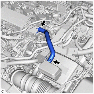 (a) Check the PCV hose connections.
(b) Check the PCV valve. Click here
OK: PCV hose and PCV valve are connected correctly and are not damaged.
| NG |
| REPAIR OR REPLACE PCV VALVE OR HOSE |
|
OK | |
| |
(a) Check the intake system for vacuum leaks.
Click here OK: No leaks from the intake system.
HINT: Perform "Inspection After Repair" after repairing or replacing the intake system.
Click here
| NG |
| REPAIR OR REPLACE INTAKE SYSTEM |
|
OK | |
| |
| 4. |
PERFORM ACTIVE TEST USING TECHSTREAM (CONTROL THE EGR STEP POSITION) |
(a) Connect the Techstream to the DLC3. (b) Turn the power switch on (IG).
(c) Turn the Techstream on. (d) Put the engine in Inspection Mode (Maintenance Mode). Powertrain > Hybrid Control > Utility
|
Tester Display | | Inspection Mode |
(e) Start the engine and warm it up until the engine coolant temperature is 75°C (167°F) or higher.
HINT: The A/C switch and all accessories should be off. (f)
Enter the following menus: Powertrain / Engine / Active Test / Control
the EGR Step Position / Data List / Intake Manifold Absolute Pressure ,
Coolant Temperature and Engine Independent. Powertrain > Engine > Active Test
|
Active Test Display | |
Control the EGR Step Position |
|
Data List Display | |
Intake Manifold Absolute Pressure | |
Coolant Temperature | |
Engine Independent | (g)
Confirm that the value of Data List item Engine Independent is
"Operate" then check the value of Intake Manifold Absolute Pressure
while performing the Active Test.
NOTICE:
- Make sure that the value of Data List item Engine Independent is "Operate" while performing the Active Test.
- Do not leave the EGR valve open for 10 seconds or more during the Active Test.
- Be sure to return the EGR valve to step 0 when the Active Test is completed.
- Do not open the EGR valve 30 steps or more during the Active Test.
OK: The value of
Intake Manifold Absolute Pressure changes in response to the EGR step
position when the value of Engine Independent is "Operate". Standard: |
- | Control the EGR Step Position (Active Test) | |
0 Steps | 0 to 30 Steps | |
Intake Manifold Absolute Pressure (Data List) |
(EGR valve is fully closed) |
Intake Manifold Absolute Pressure value is at least +10 kPa (1.45 psi) higher than when EGR valve is fully closed |
HINT:
- If the value of Data List item Engine Independent is "Not Opr" when the
engine is idling, charge control is being performed. Perform the Active
Test after charge control is complete ("Operate" is displayed).
- While performing the Active Test, if the increase in the value of Intake
Manifold Absolute Pressure is small, the EGR valve assembly may be
malfunctioning.
- Even if the EGR valve assembly is malfunctioning, rough idling or an
increase in the value of Intake Manifold Absolute Pressure may occur
while performing the Active Test. However, the amount that the value of
Intake Manifold Absolute Pressure increases will be smaller than normal.
| OK |
| GO TO STEP 6 |
|
NG | |
| |
| 5. |
INSPECT EGR VALVE ASSEMBLY | (a) Remove the EGR valve assembly.
Click here (b) Check if the EGR valve is stuck open.
OK: EGR valve is tightly closed. HINT: Perform "Inspection After Repair" after replacing the EGR valve assembly.
Click here
| NG |
| REPLACE EGR VALVE ASSEMBLY |
|
OK | |
| |
| 6. |
INSPECT THROTTLE BODY WITH MOTOR ASSEMBLY (THROTTLE VALVE) |
(a) Check the throttle body with motor assembly condition. OK:
Throttle valve is not contaminated with foreign matter and moves smoothly.
HINT: Perform "Inspection After Repair" after replacing the throttle body with motor assembly.
Click here
| NG |
| REPLACE THROTTLE BODY WITH MOTOR ASSEMBLY |
|
OK | |
| |
(a) Connect the Techstream to the DLC3.
(b) Turn the power switch on (IG). (c) Turn the Techstream on. (d) Clear the DTCs. Powertrain > Engine > Clear DTCs
(e) Turn the power switch off and wait for at least 30 seconds.
|
NEXT | |
| |
| 8. |
CONFIRM WHETHER DTC OUTPUT RECURS (DTC P050500) |
(a) Drive the vehicle in accordance with the driving pattern described in Confirmation Driving Pattern.
(b) Enter the following menus: Powertrain / Engine / Trouble Codes. (c) Read the pending DTCs. Powertrain > Engine > Trouble Codes
|
Result | Proceed to | |
DTCs are not output | A | |
DTC P050500 is output |
B |
| A |
| END |
| B |
| REPLACE ECM | |
 Evaporative Emission System Pressure Sensor/Switch Circuit Short to Ground (P045011,P045015,P04502F)
