MONITOR DESCRIPTION The auxiliary battery supplies electricity to the ECM even when the power switch is off. This power allows the ECM to store data such as DTC history, Freeze Frame Data and fuel trim values. If the auxiliary battery voltage falls below a minimum level, the memory is cleared and the ECM determines that there is a malfunction in the power supply circuit. The ECM will illuminate the MIL and store this DTC.
MONITOR STRATEGY
TYPICAL ENABLING CONDITIONS
TYPICAL MALFUNCTION THRESHOLDS
CONFIRMATION DRIVING PATTERN HINT:
WIRING DIAGRAM 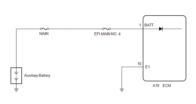 CAUTION / NOTICE / HINT NOTICE:
HINT: Read Freeze Frame Data using the Techstream. The ECM records vehicle and driving condition information as Freeze Frame Data the moment a DTC is stored. When troubleshooting, Freeze Frame Data can help determine if the vehicle was moving or stationary, if the engine was warmed up or not, if the air fuel ratio was lean or rich, and other data from the time the malfunction occurred. PROCEDURE
(a) Inspect the auxiliary battery. Click here OK: Auxiliary battery voltage is between 11 to 14 V.
(a) Check that the auxiliary battery terminals are not loose or corroded. Click here OK: Auxiliary battery terminals are not loose or corroded.
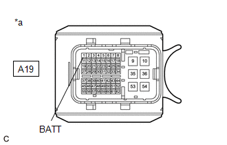
(a) Disconnect the ECM connector. (b) Measure the voltage according to the value(s) in the table below. Standard Voltage:
(a) Connect the Techstream to the DLC3. (b) Turn the power switch on (IG). (c) Turn the Techstream on. (d) Clear the DTCs. Powertrain > Engine > Clear DTCs(e) Turn the power switch off and wait for at least 30 seconds.
(a) Drive the vehicle in accordance with the driving pattern described in Confirmation Driving Pattern. (b) Enter the following menus: Powertrain / Engine / Trouble Codes. (c) Read the DTCs. Powertrain > Engine > Trouble Codes
|
Toyota Avalon (XX50) 2019-2022 Service & Repair Manual > Lane Departure Alert System (w/ Steering Control)(for Hv Model): Vehicle Speed Sensor Circuit (C1AA3)
DESCRIPTION The forward recognition camera receives vehicle speed signals from the skid control ECU (brake booster with master cylinder assembly). If the skid control ECU (brake booster with master cylinder assembly) receives a vehicle speed sensor malfunction signal, it informs the forward recognit ...


