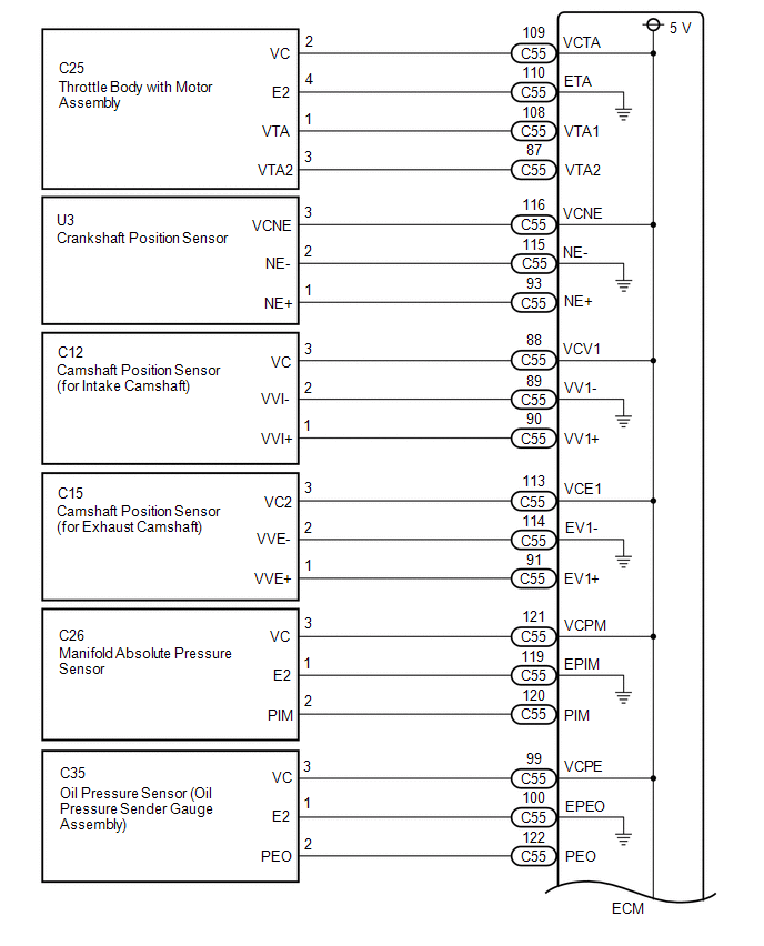
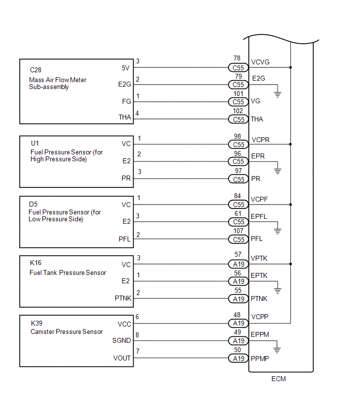
DESCRIPTION The ECM constantly generates a 5 V power source voltage from the auxiliary battery voltage supplied to the +B, +B2 (BATT) terminals to operate the microprocessor. The ECM also provides this power to the sensors through the VC output circuit. 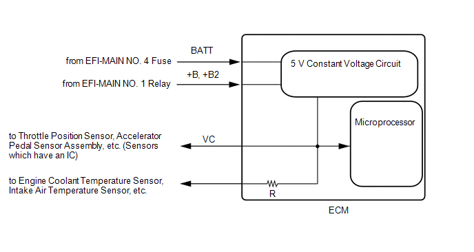 When the VC circuit has a short circuit, the microprocessor in the ECM and sensors that are supplied power through the VC circuit are deactivated because power is not supplied from the VC circuit. When the system is in this condition, it will not start. WIRING DIAGRAM
CAUTION / NOTICE / HINT NOTICE: Check the fuses for circuits related to this system before performing the following inspection procedure. PROCEDURE
(a) Connect the Techstream to the DLC3. (b) Turn the power switch on (IG). (c) Turn the Techstream on. (d) Check the communication between the Techstream and ECM. HINT: It can be checked using the "Engine" item of the Data List.
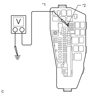
(a) Turn the power switch on (IG). (b) Measure the voltage according to the value(s) in the table below. Standard Voltage:
HINT:
(a) Disconnect the throttle body with motor assembly connector. (b) Turn the power switch on (IG). (c) Turn the Techstream on. (d) Check the communication between the Techstream and ECM. HINT: It can be checked using the "Engine" item of the Data List.
HINT: Perform "Inspection After Repair" after replacing the throttle body with motor assembly. Click here
(a) Disconnect the crankshaft position sensor connector. (b) Turn the power switch on (IG). (c) Turn the Techstream on. (d) Check the communication between the Techstream and ECM. HINT: It can be checked using the "Engine" item of the Data List.
(a) Disconnect the camshaft position sensor (for intake camshaft) connector. (b) Turn the power switch on (IG). (c) Turn the Techstream on. (d) Check the communication between the Techstream and ECM. HINT: It can be checked using the "Engine" item of the Data List.
(a) Disconnect the manifold absolute pressure sensor connector. (b) Turn the power switch on (IG). (c) Turn the Techstream on. (d) Check the communication between the Techstream and ECM. HINT: It can be checked using the "Engine" item of the Data List.
(a) Disconnect the camshaft position sensor (for exhaust camshaft) connector. (b) Turn the power switch on (IG). (c) Turn the Techstream on. (d) Check the communication between the Techstream and ECM. HINT: It can be checked using the "Engine" item of the Data List.
(a) Disconnect the oil pressure sensor (oil pressure sender gauge assembly) connector. (b) Turn the power switch on (IG). (c) Turn the Techstream on. (d) Check the communication between the Techstream and ECM. HINT: It can be checked using the "Engine" item of the Data List.
(a) Disconnect the fuel pressure sensor (for high pressure side) connector. (b) Turn the power switch on (IG). (c) Turn the Techstream on. (d) Check the communication between the Techstream and ECM. HINT: It can be checked using the "Engine" item of the Data List.
HINT: Perform "Inspection After Repair" after replacing the fuel pressure sensor (for high pressure side). Click here
(a) Disconnect the fuel pressure sensor (for low pressure side) connector. (b) Turn the power switch on (IG). (c) Turn the Techstream on. (d) Check the communication between the Techstream and ECM. HINT: It can be checked using the "Engine" item of the Data List.
HINT: Perform "Inspection After Repair" after replacing the fuel pressure sensor (for low pressure side). Click here
(a) Disconnect the mass air flow meter sub-assembly connector. (b) Turn the power switch on (IG). (c) Turn the Techstream on. (d) Check the communication between the Techstream and ECM. HINT: It can be checked using the "Engine" item of the Data List.
HINT: Perform "Inspection After Repair" after replacing the mass air flow meter sub-assembly. Click here
(a) Disconnect the canister pump module connector. (b) Turn the power switch on (IG). (c) Turn the Techstream on. (d) Check the communication between the Techstream and ECM. HINT: It can be checked using the "Engine" item of the Data List.
(a) Disconnect the fuel tank pressure sensor connector. (b) Turn the power switch on (IG). (c) Turn the Techstream on. (d) Check the communication between the Techstream and ECM. HINT: It can be checked using the "Engine" item of the Data List.
(a) Disconnect the throttle body with motor assembly connector. (b) Disconnect the crankshaft position sensor connector. (c) Disconnect the camshaft position sensor (for intake camshaft) connector. (d) Disconnect the manifold absolute pressure sensor connector. (e) Disconnect the camshaft position sensor (for exhaust camshaft) connector. (f) Disconnect the oil pressure sensor (oil pressure sender gauge assembly) connector. (g) Disconnect the fuel pressure sensor (for high pressure side) connector. (h) Disconnect the fuel pressure sensor (for low pressure side) connector. (i) Disconnect the mass air flow meter sub-assembly connector. (j) Disconnect the canister pump module connector. (k) Disconnect the fuel tank pressure sensor connector. (l) Disconnect the ECM connectors. (m) Measure the resistance according to the value(s) in the table below. Standard Resistance:
(n) Remove the VVT, EFI-MAIN NO. 2 and EFI-MAIN NO. 3 relays from the No. 1 engine room relay block and No. 1 junction block assembly. HINT: Remove the VVT, EFI-MAIN NO. 2 and EFI-MAIN NO. 3 relays connected between the checked terminals as the coil inside the relay influences the measurement value. (o) Measure the resistance according to the value(s) in the table below. Standard Resistance:
|
Toyota Avalon (XX50) 2019-2022 Service & Repair Manual > Front Door Belt Moulding: Installation
INSTALLATION CAUTION / NOTICE / HINT HINT: Use the same procedure for the RH side and LH side. The following procedure is for the LH side. PROCEDURE 1. PRECAUTION NOTICE: After turning the engine switch (for Gasoline Model) or power switch (for HV Model) off, waiting time may be required before disc ...