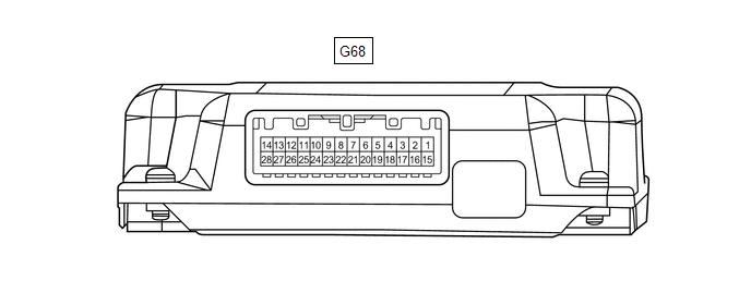
|
Terminal No. (Symbol) | Wiring Color |
Terminal Description | Condition |
Specified Condition |
|
G68-1 (CANH) | P |
CAN communication signal |
- | - |
|
G68-2 (ACK1) | V |
Serial communication (UART) signal |
- | - |
|
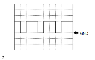
G68-3 (NEI) - G68-28 (GND) |
LA-B - W-B | Engine pulse signal |
Idling with warm engine |
Pulse generation (See waveform 1) |
|
G68-5 (MC3+) - G68-28 (GND) |
R - W-B | Active noise control microphone input signal |
No. 3 active noise control microphone tapped with finger |
Pulse generation |
|
G68-6 (MC2+) - G68-28 (GND) |
B - W-B | Active noise control microphone input signal |
No. 2 active noise control microphone tapped with finger |
Pulse generation |
|
G68-7 (MC1+) - G68-28 (GND) |
V - W-B | Active noise control microphone input signal |
No. 1 active noise control microphone tapped with finger |
Pulse generation |
|
G68-10 (CH3+) - G68-28 (GND) |
SB - W-B | Active noise control microphone output signal |
Active noise control system operating |
Pulse generation |
|
G68-11 (CH2+) - G68-28 (GND) |
L - W-B | Active noise control microphone output signal |
Active noise control system operating |
Pulse generation |
|
G68-12 (CH1+) - G68-28 (GND) |
Y - W-B | Active noise control microphone output signal |
Active noise control system operating |
Pulse generation |
|
G68-13 (ACC) - G68-28 (GND) |
P - W-B | Power source (ACC) |
Engine switch on (ACC) |
11 to 14 V |
|
G68-14 (+B) - G68-28 (GND) |
LA-G - W-B | Power source |
Always | 11 to 14 V |
|
G68-15 (CANL) | W |
CAN communication signal |
- | - |
|
G68-16 (ACK2) | BE |
Serial communication (UART) signal |
- | - |
|
G68-17 (ACNT) - G68-28 (GND) |
SB - W-B |
Active noise control system control signal |
Engine switch on (IG) |
Below 1 V |
|
Engine switch on (ACC) |
4.5 V or higher |
|
G68-19 (MC3-) - G68-28 (GND) |
G - W-B | Active noise control microphone input signal |
Always | Below 1 Ω |
|
G68-20 (MC2-) - G68-28 (GND) |
P - W-B | Active noise control microphone input signal |
Always | Below 1 Ω |
|
G68-21 (MC1-) - G68-28 (GND) |
LG - W-B | Active noise control microphone input signal |
Always | Below 1 Ω |
|
G68-24 (CH3-) - G68-28 (GND) |
P - W-B | Active noise control microphone output signal |
Active noise control system operating |
Pulse generation |
|
G68-25 (CH2-) - G68-28 (GND) |
V - W-B | Active noise control microphone output signal |
Active noise control system operating |
Pulse generation |
|
G68-26 (CH1-) - G68-28 (GND) |
LG - W-B | Active noise control microphone output signal |
Active noise control system operating |
Pulse generation |
|
G68-27 (IGN) - G68-28 (GND) |
LA-SB - W-B | Power source (IG) |
Engine switch on (IG) |
11 to 14 V |
|
G68-28 (GND) - Body ground |
W-B - Body ground | Ground |
Always | Below 1 Ω |