DESCRIPTION The vehicle-to-vehicle distance control switch is used to set the distance for vehicle-to-vehicle distance control mode. The vehicle-to-vehicle distance control switch is installed in the steering pad switch assembly. The vehicle-to-vehicle distance set value can be changed by operating the vehicle-to-vehicle distance control switch while the dynamic radar cruise control system is controlling vehicle speed in vehicle-to-vehicle distance control mode. WIRING DIAGRAM 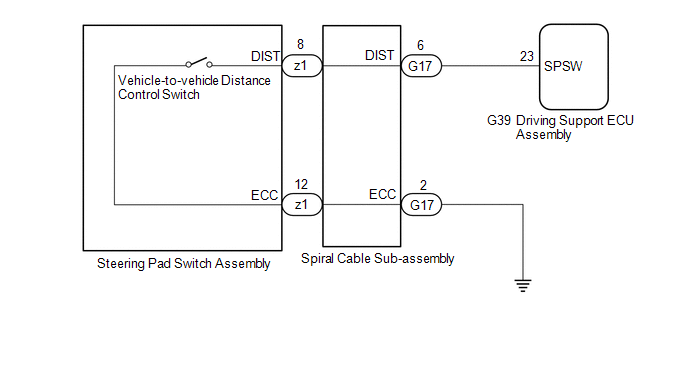 CAUTION / NOTICE / HINT NOTICE:
PROCEDURE
(a) Connect the Techstream to the DLC3. (b) Turn the engine switch on (IG). (c) Turn the Techstream on. (d) Enter the following menus: Powertrain / Radar Cruise 2 / Data List. (e) Read the Data List according to the display on the Techstream. Powertrain > Radar Cruise2 > Data List
OK: When the vehicle-to-vehicle distance control switch is operated, the display changes as shown above.
(a) Remove the steering pad switch assembly. Click here (b) Inspect the steering pad switch assembly. Click here
(a) Remove the spiral cable sub-assembly. Click here (b) Inspect the spiral cable sub-assembly. Click here
(a) Disconnect the G17 spiral cable sub-assembly connector. (b) Disconnect the G39 driving support ECU assembly connector. (c) Measure the resistance according to the value(s) in the table below. Standard Resistance:
(d) Connect the G39 driving support ECU assembly connector. (e) Connect the G17 spiral cable sub-assembly connector.
|
Toyota Avalon (XX50) 2019-2022 Service & Repair Manual > Automatic Transaxle Unit: Disassembly
DISASSEMBLY PROCEDURE 1. REMOVE TRANSMISSION CONTROL SHAFT LEVER (a) Remove the nut, washer and transmission control shaft lever from the manual valve lever shaft sub-assembly. 2. REMOVE PARK/NEUTRAL POSITION SWITCH ASSEMBLY (a) Remove the 2 bolts and park/neutral position switch assembly from the a ...


