DESCRIPTION A battery
current sensor is installed to the positive (+) terminal side of the HV
battery and detects current flowing from the HV battery. The battery
current sensor outputs voltage, which changes between 0 and 5 V
according to the detected amperage, to the IB0 terminal of the battery
voltage sensor. The battery voltage sensor sends signals to the hybrid
vehicle control ECU. The hybrid vehicle control ECU determines the
charging and discharging amount of the HV battery based on the received
signals and calculates the SOC of the HV battery through the accumulated
amperage. 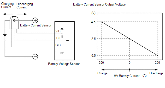 |
DTC No. | Detection Item |
DTC Detection Condition | Trouble Area |
MIL | Warning Indicate | |
P0ABF11 | Hybrid/EV Battery Current Sensor "A" Circuit Short to Ground |
The battery current sensor output voltage is excessively low. (1 trip detection logic) |
- Battery voltage sensor
- HV battery junction block assembly
- Wire harness or connector
| Comes on |
Master Warning Light: Comes on | |
P0ABF15 | Hybrid/EV Battery Current Sensor "A" Circuit Short to Auxiliary Battery or Open |
The battery current sensor output voltage is excessively high.
(1 trip detection logic) |
- Battery voltage sensor
- HV battery junction block assembly
- Wire harness or connector
| Comes on |
Master Warning Light: Comes on | |
P1CBB12 | Hybrid/EV Battery Current Sensor Power Supply Circuit Short to Auxiliary Battery |
Power source voltage of the battery current sensor is excessively high.
(1 trip detection logic) |
- Battery voltage sensor
- HV battery junction block assembly
- Wire harness or connector
| Comes on |
Master Warning Light: Comes on | |
P1CBB14 | Hybrid/EV Battery Current Sensor Power Supply Circuit Short to Ground or Open |
Power source voltage of the battery current sensor is excessively low.
(1 trip detection logic) |
- Battery voltage sensor
- HV battery junction block assembly
- Wire harness or connector
| Comes on |
Master Warning Light: Comes on | Related Data List |
DTC No. | Data List | |
P0ABF11 | Hybrid Battery Current*1 | |
P0ABF15 | | P1CBB12 | |
P1CBB14 | HINT: *1: The value of "Hybrid Battery Current" will be approximately 0 A when the power switch is on (IG) (READY off). MONITOR DESCRIPTION
If
the battery voltage sensor detects a malfunction in the battery current
sensor, the hybrid vehicle control ECU will illuminate the MIL and
store a DTC. MONITOR STRATEGY |
Related DTCs | P0AC1 (INF P0ABF11): Current sensor circuit malfunction (GND short)
P0AC2 (INF P0ABF15): Current sensor circuit malfunction (open) P1CBD (INF P1CBB12): Power supply circuit for current sensor malfunction (+B short)
P1CBC (INF P1CBB14): Power supply circuit for current sensor malfunction (GND short) | |
Required sensors/components | Battery current sensor | |
Frequency of operation | Continuous | |
Duration | TMC's intellectual property | |
MIL operation | Immediately | |
Sequence of operation | None | TYPICAL ENABLING CONDITIONS |
The monitor will run whenever the following DTCs are not stored |
TMC's intellectual property | | Other conditions belong to TMC's intellectual property |
- | TYPICAL MALFUNCTION THRESHOLDS |
TMC's intellectual property | - | COMPONENT OPERATING RANGE |
Battery voltage sensor | DTC P0AC1 (INF P0ABF11) is not detected
DTC P0AC2 (INF P0ABF15) is not detected DTC P1CBD (INF P1CBB12) is not detected
DTC P1CBC (INF P1CBB14) is not detected | CONFIRMATION DRIVING PATTERN
HINT:
- After repair has been completed, clear the DTC and then check that the
vehicle has returned to normal by performing the following All Readiness
check procedure.
Click here 
- When clearing the permanent DTCs, refer to the "CLEAR PERMANENT DTC" procedure.
Click here
- Connect the Techstream to the DLC3.
- Turn the power switch on (IG) and turn the Techstream on.
- Clear the DTCs (even if no DTCs are stored, perform the clear DTC procedure).
- Turn the power switch off and wait for 2 minutes or more.
- Turn the power switch on (IG) and turn the Techstream on.
- With power switch on (IG) and wait for 10 seconds or more.[*1]
HINT:
[*1]: Normal judgment procedure.
The normal judgment procedure is used to complete DTC judgment and also used when clearing permanent DTCs.
- Enter the following menus: Powertrain / Hybrid Control / Utility / All Readiness.
- Check the DTC judgment result.
HINT:
- If the judgment result shows NORMAL, the system is normal.
- If the judgment result shows ABNORMAL, the system has a malfunction.
- If the judgment result shows INCOMPLETE or N/A, perform the normal judgment procedure again.
WIRING DIAGRAM
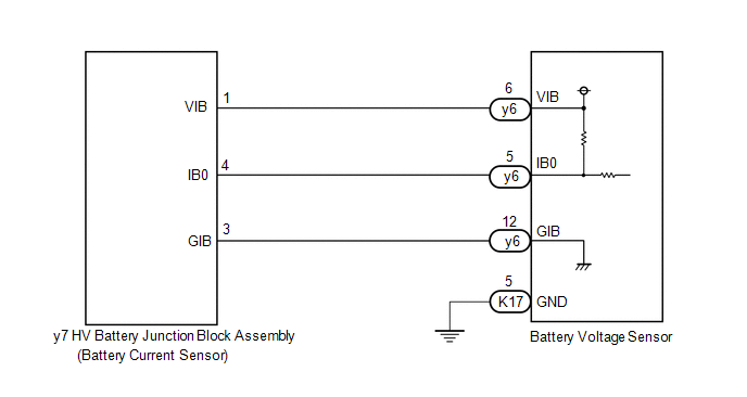 Refer to the wiring diagram for DTC P0AFC00.
Click here CAUTION / NOTICE / HINT
CAUTION:
NOTICE: After
turning the power switch off, waiting time may be required before
disconnecting the cable from the negative (-) auxiliary battery
terminal. Therefore, make sure to read the disconnecting the cable from
the negative (-) auxiliary battery terminal notices before proceeding
with work. Click here PROCEDURE
| 1. |
CHECK DTC OUTPUT (HYBRID CONTROL) | (a) Connect the Techstream to the DLC3.
(b) Turn the power switch on (IG). (c) Enter the following menus: Powertrain / Hybrid Control / Trouble Codes.
(d) Check for DTCs. Powertrain > Hybrid Control > Trouble Codes
|
Result | Proceed to | |
P0AFC00, P0AFC96 or P308A12 is not output. |
A | | P0AFC00, P0AFC96 or P308A12 is output. |
B | (e) Turn the power switch off.
| B |
 | GO TO DTC CHART (HYBRID CONTROL SYSTEM) |
|
A |
 | |
| 2. |
CHECK BATTERY VOLTAGE SENSOR (IGCT VOLTAGE) |
Click here
| NG |
| REPAIR OR REPLACE HARNESS OR CONNECTOR (BATTERY VOLTAGE SENSOR POWER SOURCE CIRCUIT) |
|
OK | |
| |
| 3. |
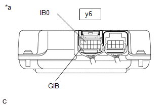
CHECK HARNESS AND CONNECTOR (BATTERY VOLTAGE SENSOR - HV BATTERY JUNCTION BLOCK ASSEMBLY) |
CAUTION: Be sure to wear insulated gloves. (a) Check that the service plug grip is not installed.
NOTICE: After
removing the service plug grip, do not turn the power switch on
(READY), unless instructed by the repair manual because this may cause a
malfunction. (b) Remove the No. 1 HV battery cover panel RH. Click here
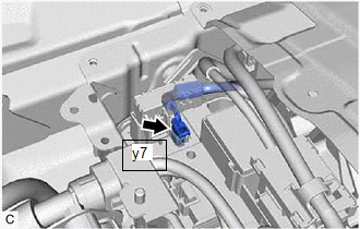
| (c) Disconnect the y7 battery current sensor connector. NOTICE:
Before disconnecting the connector, check that it is not loose or disconnected. |
|
(d) Remove the No. 1 hybrid battery exhaust duct. Click here
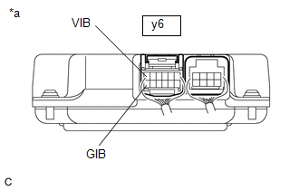
(e) Disconnect the y6 battery voltage sensor connector.
NOTICE: Before disconnecting the connector, check that it is not loose or disconnected.
| (f) Measure the resistance according to the value(s) in the tables below.
Standard Resistance (Check for Open): |
Tester Connection | Condition |
Specified Condition | |
y6-5 (IB0) - y7-4 (IB0) |
Power switch off |
Below 1 Ω | |
y6-12 (GIB) - y7-3 (GIB) |
Power switch off |
Below 1 Ω | |
y6-6 (VIB) - y7-1 (VIB) |
Power switch off |
Below 1 Ω | Standard Resistance (Check for Short): |
Tester Connection | Condition |
Specified Condition | |
y6-5 (IB0) or y7-4 (IB0) - Body ground and other terminals |
Power switch off |
10 kΩ or higher | |
y6-12 (GIB) or y7-3 (GIB) - Body ground and other terminals |
Power switch off |
10 kΩ or higher | |
y6-6 (VIB) or y7-1 (VIB) - Body ground and other terminals |
Power switch off |
10 kΩ or higher | HINT: As the battery harness is not available as a supply part, if the harness cannot be repaired, replace the HV battery. |
 |
|
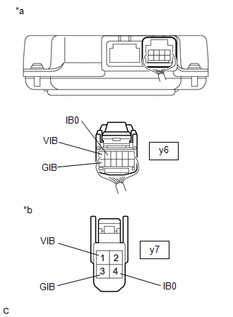
*a | Rear view of wire harness connector
(to Battery Voltage Sensor) | |
*b | Front view of wire harness connector
(to HV Battery Junction Block Assembly (Battery Current Sensor)) | | |
(g) Reconnect the y6 battery voltage sensor connector. (h) Install the No. 1 hybrid battery exhaust duct.
(i) Reconnect the y7 battery current sensor connector. (j) Install the No. 1 HV battery cover panel RH.
| NG |
| REPLACE HYBRID BATTERY THERMISTOR |
|
OK | |
| |
| 4. |
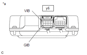
CHECK BATTERY VOLTAGE SENSOR (VIB VOLTAGE) |
CAUTION: Be sure to wear insulated gloves. (a) Check that the service plug grip is not installed.
NOTICE: After
removing the service plug grip, do not turn the power switch on
(READY), unless instructed by the repair manual because this may cause a
malfunction. (b) Remove the No. 1 hybrid battery exhaust duct. Click here
(c) Connect the cable to the negative (-) auxiliary battery terminal.
(d) Turn the power switch on (IG).
| (e) Measure the voltage according to the value(s) in the table below.
Standard Voltage: |
Tester Connection | Condition |
Specified Condition | |
y6-6 (VIB) - y6-12 (GIB) |
Power switch on (IG) |
4.6 to 5.4 V | NOTICE: Turning
the power switch on (IG) with the service plug grip removed causes
other DTCs to be stored. Clear the DTCs after performing this
inspection. |
 |
|
*a | Component with harness connected (Battery Voltage Sensor) | | |
(f) Turn the power switch off. (g) Disconnect the cable from the negative (-) auxiliary battery terminal.
(h) Install the No. 1 hybrid battery exhaust duct.
| NG |
| GO TO STEP 9 |
|
OK | |
| |
| 5. |
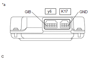
CHECK BATTERY VOLTAGE SENSOR (GIB - GND) |
CAUTION: Be sure to wear insulated gloves. (a) Check that the service plug grip is not installed.
NOTICE: After
removing the service plug grip, do not turn the power switch on
(READY), unless instructed by the repair manual because this may cause a
malfunction. (b) Remove the No. 1 hybrid battery exhaust duct. Click here
(c) Disconnect the y6 and K17 battery voltage sensor connectors.
NOTICE: Before disconnecting the connector, check that it is not loose or disconnected.
| (d) Measure the resistance according to the value(s) in the tables below.
Standard Resistance: |
Tester Connection | Condition |
Specified Condition | |
y6-12 (GIB) - K17-5 (GND) |
Power switch off |
Below 1 Ω | |
 |
|
*a | Component without harness connected
(Battery Voltage Sensor) | | |
(e) Reconnect the y6 and K17 battery voltage sensor connectors. (f) Install the No. 1 hybrid battery exhaust duct.
| NG |
| REPLACE BATTERY VOLTAGE SENSOR |
|
OK | |
| |
| 6. |
CHECK BATTERY VOLTAGE SENSOR (BATTERY CURRENT SENSOR OUTPUT VOLTAGE) |
CAUTION: Be sure to wear insulated gloves. (a) Check that the service plug grip is not installed.
NOTICE: After
removing the service plug grip, do not turn the power switch on
(READY), unless instructed by the repair manual because this may cause a
malfunction. (b) Remove the No. 1 hybrid battery exhaust duct. Click here
(c) Connect the cable to the negative (-) auxiliary battery terminal.
(d) Turn the power switch on (IG).
| (e) Measure the voltage according to the value(s) in the table below.
Standard Voltage: |
Tester Connection | Condition |
Specified Condition | |
y6-5 (IB0) - y6-12 (GIB) |
Power switch on (IG) |
2.46 to 2.54 V | NOTICE:
Turning
the power switch on (IG) with the service plug grip removed causes
other DTCs to be stored. Clear the DTCs after performing this
inspection. |
 |
|
*a | Component with harness connected (Battery Voltage Sensor) | | |
(f) Turn the power switch off. (g) Disconnect the cable from the negative (-) auxiliary battery terminal.
(h) Install the No. 1 hybrid battery exhaust duct.
|
Result | Proceed to | |
OK | A | |
NG(Voltage is outside the specified value and 0.4 V or more.) |
B | | NG(Voltage is outside the specified value and less than 0.4 V.) |
C |
| A |
| REPLACE BATTERY VOLTAGE SENSOR |
| C |
| GO TO STEP 8 |
|
B | |
| |
| 7. |
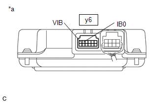
CHECK BATTERY VOLTAGE SENSOR (VIB - IB0) |
CAUTION: Be sure to wear insulated gloves. (a) Check that the service plug grip is not installed.
NOTICE: After
removing the service plug grip, do not turn the power switch on
(READY), unless instructed by the repair manual because this may cause a
malfunction. (b) Remove the No. 1 hybrid battery exhaust duct. Click here
(c) Disconnect the y6 battery voltage sensor connector.
NOTICE: Before disconnecting the connector, check that it is not loose or disconnected.
| (d) Measure the resistance according to the value(s) in the tables below. |
Tester Connection | Condition | |
y6-6 (VIB) - y6-5 (IB0) |
Power switch off | |
 |
|
*a | Component without harness connected
(Battery Voltage Sensor) | | |
(e) Reconnect the y6 battery voltage sensor connector. (f) Install the No. 1 hybrid battery exhaust duct.
|
Result | Proceed to | |
Below 1 Ω | A | |
Other than above | B |
| A |
| REPLACE BATTERY VOLTAGE SENSOR |
| B |
| REPLACE HV BATTERY JUNCTION BLOCK ASSEMBLY |
| 8. |
CHECK BATTERY VOLTAGE SENSOR (BATTERY CURRENT SENSOR OUTPUT VOLTAGE) |
CAUTION: Be sure to wear insulated gloves. (a) Check that the service plug grip is not installed.
NOTICE: After
removing the service plug grip, do not turn the power switch on
(READY), unless instructed by the repair manual because this may cause a
malfunction. (b) Remove the No. 1 HV battery cover panel RH. Click here
| (c) Disconnect the y7 battery current sensor connector. NOTICE:
Before disconnecting the connector, check that it is not loose or disconnected. |
|
(d) Remove the No. 1 hybrid battery exhaust duct. Click here
(e) Connect the cable to the negative (-) auxiliary battery terminal.
(f) Turn the power switch on (IG).
| (g) Measure the voltage according to the value(s) in the table below.
Standard Voltage: |
Tester Connection | Condition |
Specified Condition | |
y6-5 (IB0) - y6-12 (GIB) |
Power switch on (IG) |
4.6 to 5.4 V | NOTICE: Turning
the power switch on (IG) with the service plug grip removed causes
other DTCs to be stored. Clear the DTCs after performing this
inspection. |
 |
|
*a | Component with harness connected (Battery Voltage Sensor) | | |
(h) Turn the power switch off. (i) Disconnect the cable from the negative (-) auxiliary battery terminal.
(j) Install the No. 1 hybrid battery exhaust duct. (k) Reconnect the y7 battery current sensor connector.
(l) Install the No. 1 HV battery cover panel RH.
| OK |
| REPLACE HV BATTERY JUNCTION BLOCK ASSEMBLY |
| NG |
| REPLACE BATTERY VOLTAGE SENSOR |
| 9. |
CHECK BATTERY VOLTAGE SENSOR (VIB VOLTAGE) |
CAUTION: Be sure to wear insulated gloves. (a) Check that the service plug grip is not installed.
NOTICE: After
removing the service plug grip, do not turn the power switch on
(READY), unless instructed by the repair manual because this may cause a
malfunction. (b) Remove the No. 1 HV battery cover panel RH. Click here
| (c) Disconnect the y7 battery current sensor connector. NOTICE:
Before disconnecting the connector, check that it is not loose or disconnected. |
|
(d) Remove the No. 1 hybrid battery exhaust duct. Click here
(e) Connect the cable to the negative (-) auxiliary battery terminal.
(f) Turn the power switch on (IG).
| (g) Measure the voltage according to the value(s) in the table below.
Standard Voltage: |
Tester Connection | Condition |
Specified Condition | |
y6-6 (VIB) - y6-12 (GIB) |
Power switch on (IG) |
4.6 to 5.4 V | NOTICE: Turning
the power switch on (IG) with the service plug grip removed causes
other DTCs to be stored. Clear the DTCs after performing this
inspection. |
 |
|
*a | Component with harness connected (Battery Voltage Sensor) | | |
(h) Turn the power switch off. (i) Disconnect the cable from the negative (-) auxiliary battery terminal.
(j) Install the No. 1 hybrid battery exhaust duct. (k) Reconnect the y7 battery current sensor connector.
(l) Install the No. 1 HV battery cover panel RH.
| OK |
| REPLACE HV BATTERY JUNCTION BLOCK ASSEMBLY |
| NG |
| REPLACE BATTERY VOLTAGE SENSOR | |