Toyota Avalon Service & Repair Manual: Illumination Circuit

DESCRIPTION

Power is supplied to the radio and display receiver assembly and steering pad switch assembly illumination when the light control switch is in the tail or head position.

WIRING DIAGRAM

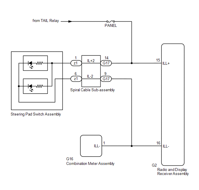
CAUTION / NOTICE / HINT

NOTICE:

  • The vehicle is equipped with a Supplemental Restraint System (SRS) which includes components such as airbags. Before servicing (including removal or installation of parts), be sure to read the precaution for Supplemental Restraint System.

    Click here

  • Inspect the fuses for circuits related to this system before performing the following procedure.

PROCEDURE

1.

CHECK ILLUMINATION

(a) Check if the illumination for the radio and display receiver assembly, steering pad switch assembly, heater control switch or others (hazard switch, transmission control switch, etc.) comes on when the light control switch is turned to the head or tail position.

Result

Proceed to

Illumination comes on for all components except steering pad switch assembly.

A

Illumination comes on for all components except radio and display receiver assembly.

B

No illumination comes on (radio and display receiver assembly, hazard switch, heater control switch, etc.).

C

B

GO TO STEP 5

C

GO TO LIGHTING SYSTEM

A

2.

CHECK HARNESS AND CONNECTOR (ILLUMINATION SIGNAL)

(a) Disconnect the G17 spiral cable sub-assembly connector.

(b) Measure the voltage according to the value(s) in the table below.

Standard Voltage:

Tester Connection

Condition

Specified Condition

G17-14 (IL+2) - Body ground

Light control switch in tail or head position

11 to 14 V

NG

REPAIR OR REPLACE HARNESS OR CONNECTOR

OK

3.

INSPECT STEERING PAD SWITCH ASSEMBLY

(a) Remove the steering pad switch assembly.

Click here

(b) Inspect the steering pad switch assembly.

Click here

NG

REPLACE STEERING PAD SWITCH ASSEMBLY

OK

4.

INSPECT SPIRAL CABLE SUB-ASSEMBLY

(a) Remove the spiral cable sub-assembly.

Click here

(b) Inspect the spiral cable sub-assembly.

Click here

OK

REPAIR OR REPLACE HARNESS OR CONNECTOR (SPIRAL CABLE SUB-ASSEMBLY - RADIO AND DISPLAY RECEIVER ASSEMBLY, COMBINATION METER ASSEMBLY)

NG

REPLACE SPIRAL CABLE SUB-ASSEMBLY

5.

CHECK HARNESS AND CONNECTOR (ILLUMINATION SIGNAL)

(a) Disconnect the G2 radio and display receiver assembly connector.

(b) Measure the voltage according to the value(s) in the table below.

Standard Voltage:

Tester Connection

Condition

Specified Condition

G2-15 (ILL+) - Body ground

Light control switch in tail or head position

11 to 14 V

NG

REPAIR OR REPLACE HARNESS OR CONNECTOR

OK

6.

CHECK HARNESS AND CONNECTOR (RADIO AND DISPLAY RECEIVER ASSEMBLY - COMBINATION METER ASSEMBLY)

(a) Disconnect the G2 radio and display receiver assembly connector.

(b) Disconnect the G16 combination meter assembly connector.

(c) Measure the resistance according to the value(s) in the table below.

Standard Resistance:

Tester Connection

Condition

Specified Condition

G2-16 (ILL-) - G16-1 (ILL-)

Always

Below 1 Ω

G2-16 (ILL-) or G16-1 (ILL-) - Body ground

Always

10 kΩ or higher

OK

PROCEED TO NEXT SUSPECTED AREA SHOWN IN PROBLEM SYMPTOMS TABLE

NG

REPAIR OR REPLACE HARNESS OR CONNECTOR

    How To Proceed With Troubleshooting

    Illumination for Panel Switch does not Come on with Tail Switch ON

    See More:

    Toyota Avalon Service & Repair Manual > Electronically Controlled Brake System(for Gasoline Model): TRAC does not Operate
    DESCRIPTION When TRAC or VSC is operating, the skid control ECU (brake actuator assembly) blinks the slip indicator light to inform the driver that slippage occurred. When in VSC off mode, or TRAC and VSC are disabled, the multi-information display in the combination meter assembly displays "Tractio ...

    Toyota Avalon Owners Manual

    Toyota Avalon Service & Repair Manual

    © 2024 Copyright www.tavalon.net
    0.017