DESCRIPTION This circuit is from the skid control ECU (brake actuator assembly) to the radio and display receiver assembly. WIRING DIAGRAM 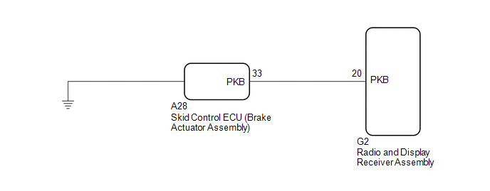 PROCEDURE
(a) Check that the brake warning light comes on when the parking brake is applied and goes off when it is released. OK: The brake warning light operates as specified above.
(a) Disconnect the G2 radio and display receiver assembly connector. (b) Disconnect the A28 skid control ECU (brake actuator assembly) connector. (c) Measure the resistance according to the value(s) in the table below. Standard Resistance:
|
Toyota Avalon (XX50) 2019-2022 Service & Repair Manual > Knock Sensor: Inspection
INSPECTION PROCEDURE 1. INSPECT KNOCK CONTROL SENSOR (a) Measure the resistance according to the value(s) in the table below. Standard Resistance: Tester Connection Condition Specified Condition 1 - 2 25°C (77°F) 120 to 280 kΩ If the result is not as specified, replace the knock control sensor. * ...


