DESCRIPTION There may be a
short circuit between one of the CAN bus lines and +B when there is no
resistance between terminal 23 (CA1H) of the central gateway ECU
(network gateway ECU) and terminal 16 (BAT) of the DLC3, or terminal 8
(CA1L) of the central gateway ECU (network gateway ECU) and terminal 16
(BAT) of the DLC3. |
Symptom | Trouble Area | |
There
is no resistance between terminal 23 (CA1H) of the central gateway ECU
(network gateway ECU) and terminal 16 (BAT) of the DLC3, or terminal 8
(CA1L) of the central gateway ECU (network gateway ECU) and terminal 16
(BAT) of the DLC3. |
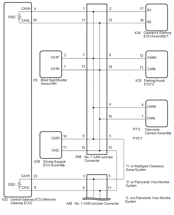
| WIRING DIAGRAM
 CAUTION / NOTICE / HINT
CAUTION: When performing the confirmation driving pattern, obey all speed limits and traffic laws.
NOTICE:
HINT:
- Before disconnecting related connectors for inspection, push in on each
connector body to check that the connector is not loose or disconnected.
- When a connector is disconnected, check that the terminals and connector body are not cracked, deformed or corroded.
PROCEDURE |
1. | CHECK FOR SHORT TO +B IN CAN BUS LINE (NO. 1 CAN JUNCTION CONNECTOR) |
(a) Disconnect the cable from the negative (-) battery terminal. (b) Disconnect the A48 No. 1 CAN junction connector.
(c) Measure the resistance according to the value(s) in the table below.
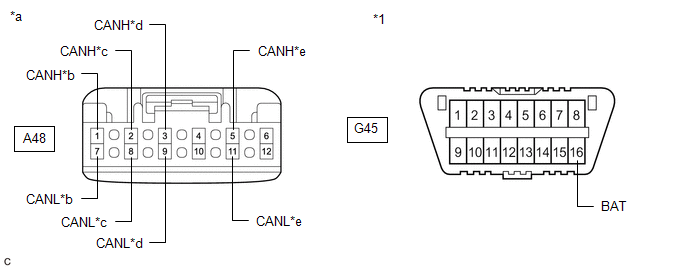
|
*1 | DLC3 |
- | - | |
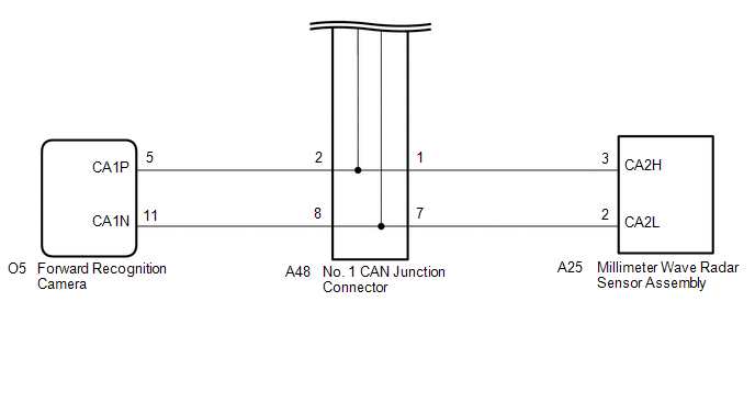
*a | Front view of wire harness connector
(to No. 1 CAN Junction Connector) |
*b | to Millimeter Wave Radar Sensor Assembly | |
*c | to Forward Recognition Camera |
*d | to Central Gateway ECU (Network Gateway ECU) | |
*e | to No. 7 CAN Junction Connector |
- | - |
Standard Resistance: |
Tester Connection | Condition |
Specified Condition | Connected to | |
A48-1 (CANH) - G45-16 (BAT) |
Cable disconnected from negative (-) battery terminal |
6 kΩ or higher |
Millimeter wave radar sensor assembly | |
A48-7 (CANL) - G45-16 (BAT) | |
A48-2 (CANH) - G45-16 (BAT) |
Cable disconnected from negative (-) battery terminal |
6 kΩ or higher |
Forward recognition camera | |
A48-8 (CANL) - G45-16 (BAT) | |
A48-3 (CANH) - G45-16 (BAT) |
Cable disconnected from negative (-) battery terminal |
6 kΩ or higher |
Central gateway ECU (network gateway ECU) | |
A48-9 (CANL) - G45-16 (BAT) | |
A48-5 (CANH) - G45-16 (BAT) |
Cable disconnected from negative (-) battery terminal |
6 kΩ or higher |
No. 7 CAN junction connector | |
A48-11 (CANL) - G45-16 (BAT) |
|
Result | Proceed to | |
OK | A | |
NG (Line to central gateway ECU (network gateway ECU)) |
B | | NG (Line to No. 7 CAN junction connector) |
C | | NG (Line to ECU or sensor) |
D |
| A |
 | REPLACE NO. 1 CAN JUNCTION CONNECTOR |
| C |
| GO TO STEP 3 |
| D |
| GO TO STEP 5 |
|
B |
 | |
| 2. |
CHECK FOR SHORT TO +B IN CAN BUS LINE (NO. 1 CAN JUNCTION CONNECTOR - CENTRAL GATEWAY ECU (NETWORK GATEWAY ECU)) |
(a) Disconnect the G52 central gateway ECU (network gateway ECU) connector.
(b) Measure the resistance according to the value(s) in the table below.
|
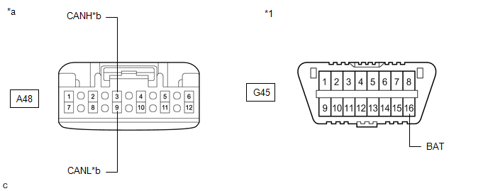
*1 | DLC3 |
- | - | |
*a | Front view of wire harness connector
(to No. 1 CAN Junction Connector) |
*b | to Central Gateway ECU (Network Gateway ECU) |
Standard Resistance: |
Tester Connection | Condition |
Specified Condition | |
A48-3 (CANH) - G45-16 (BAT) |
Cable disconnected from negative (-) battery terminal |
6 kΩ or higher | |
A48-9 (CANL) - G45-16 (BAT) |
| OK |
| REPLACE CENTRAL GATEWAY ECU (NETWORK GATEWAY ECU) |
| NG |
| REPAIR OR REPLACE CAN MAIN BUS LINE OR CONNECTOR (NO. 1 CAN JUNCTION CONNECTOR - CENTRAL GATEWAY ECU (NETWORK GATEWAY ECU)) |
| 3. |
CHECK FOR SHORT TO +B IN CAN BUS LINE (NO. 7 CAN JUNCTION CONNECTOR) |
(a) Disconnect the K66 No. 7 CAN junction connector. (b) Measure the resistance according to the value(s) in the table below.
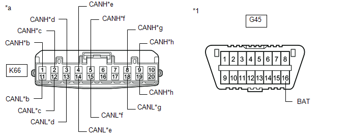
|
*1 | DLC3 |
- | - | |
*a | Front view of wire harness connector
(to No. 7 CAN Junction Connector) |
*b | to Central Gateway ECU (Network Gateway ECU) | |
*c | to Clearance Warning ECU Assembly
(w/ Intelligent Clearance Sonar System) |
*d | to Blind Spot Monitor Sensor RH | |
*e | to Television Camera Assembly |
*f | to No. 1 CAN Junction Connector | |
*g | to Parking Assist ECU
(w/ Panoramic View Monitor System) |
*h | to Driving Support ECU Assembly |
Standard Resistance: |
Tester Connection | Condition |
Specified Condition | Connected to | |
K66-1 (CANH) - G45-16 (BAT) |
Cable disconnected from negative (-) battery terminal |
6 kΩ or higher |
Central gateway ECU (network gateway ECU) | |
K66-11 (CANL) - G45-16 (BAT) | |
K66-2 (CANH) - G45-16 (BAT) |
Cable disconnected from negative (-) battery terminal |
6 kΩ or higher |
Clearance warning ECU assembly*1 | |
K66-12 (CANL) - G45-16 (BAT) | |
K66-3 (CANH) - G45-16 (BAT) |
Cable disconnected from negative (-) battery terminal |
6 kΩ or higher |
Blind spot monitor sensor RH | |
K66-13 (CANL) - G45-16 (BAT) | |
K66-4 (CANH) - G45-16 (BAT) |
Cable disconnected from negative (-) battery terminal |
6 kΩ or higher |
Television camera assembly | |
K66-14 (CANL) - G45-16 (BAT) | |
K66-5 (CANH) - G45-16 (BAT) |
Cable disconnected from negative (-) battery terminal |
6 kΩ or higher |
No. 1 CAN junction connector | |
K66-15 (CANL) - G45-16 (BAT) | |
K66-8 (CANH) - G45-16 (BAT) |
Cable disconnected from negative (-) battery terminal |
6 kΩ or higher |
Parking assist ECU*2 | |
K66-18 (CANL) - G45-16 (BAT) | |
K66-9 (CANH) - G45-16 (BAT) |
Cable disconnected from negative (-) battery terminal |
6 kΩ or higher |
Driving support ECU assembly | |
K66-19 (CANL) - G45-16 (BAT) |
- *1: w/ Intelligent Clearance Sonar System
- *2: w/ Panoramic View Monitor System
|
Result | Proceed to | |
OK | A | |
NG (Line to central gateway ECU (network gateway ECU)) |
B | | NG (Line to No. 1 CAN junction connector) |
C | | NG (Line to ECU or sensor) |
D |
| A |
| REPLACE NO. 7 CAN JUNCTION CONNECTOR |
| C |
| REPAIR OR REPLACE CAN MAIN BUS LINE OR CONNECTOR (NO. 7 CAN JUNCTION CONNECTOR - NO. 1 CAN JUNCTION CONNECTOR) |
| D |
| GO TO STEP 5 |
|
B | |
| |
| 4. |
CHECK FOR SHORT TO +B IN CAN BUS LINE (NO. 7 CAN JUNCTION CONNECTOR - CENTRAL GATEWAY ECU (NETWORK GATEWAY ECU)) |
(a) Disconnect the G52 central gateway ECU (network gateway ECU) connector.
(b) Measure the resistance according to the value(s) in the table below.
|
*1 | DLC3 |
- | - | |
*a | Front view of wire harness connector
(to No. 7 CAN Junction Connector) |
*b | to Central Gateway ECU (Network Gateway ECU) |
Standard Resistance: |
Tester Connection | Condition |
Specified Condition | |
K66-1 (CANH) - G45-16 (BAT) |
Cable disconnected from negative (-) battery terminal |
6 kΩ or higher | |
K66-11 (CANL) - G45-16 (BAT) |
| OK |
| REPLACE CENTRAL GATEWAY ECU (NETWORK GATEWAY ECU) |
| NG |
| REPAIR OR REPLACE CAN MAIN BUS LINE OR CONNECTOR (NO. 7 CAN JUNCTION CONNECTOR - CENTRAL GATEWAY ECU (NETWORK GATEWAY ECU)) |
| 5. |
CHECK FOR SHORT TO +B IN CAN BUS LINE (ECU OR SENSOR) |
(a) Reconnect all wire harness connectors. (b)
Disconnect the connector that includes terminals CANH and CANL from the
ECU or sensor to which the bus line shorted to +B is connected. Click here
 (c) Measure the resistance according to the value(s) in the table below.
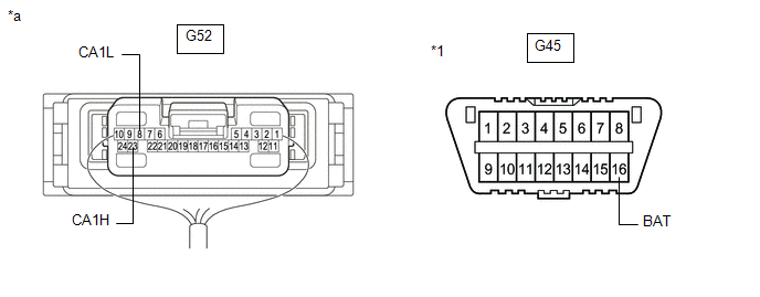
|
*1 | DLC3 |
- | - | |
*a | Component with harness connected
(Central Gateway ECU (Network Gateway ECU)) |
- | - |
Standard Resistance: |
Tester Connection | Condition |
Specified Condition | |
G52-23 (CA1H) - G45-16 (BAT) |
Cable disconnected from negative (-) battery terminal |
6 kΩ or higher | |
G52-8 (CA1L) - G45-16 (BAT) |
HINT:
- If the resistance changes to 6 kΩ or higher when the connector is
disconnected from the ECU or sensor, there may be a short in the ECU or
sensor.
- If the resistance does not become normal when the connector is
disconnected from the ECU or sensor, check for a short to +B in the wire
harness and repair or replace the wire harness or connector if
necessary.
| OK |
| REPLACE ECU OR SENSOR |
| NG |
| REPAIR OR REPLACE HARNESS OR CONNECTOR | | 

