DESCRIPTION This DTC is stored when a video or audio signal is interrupted due to auxiliary battery voltage input to the radio and display receiver assembly dropping temporarily.
WIRING DIAGRAM 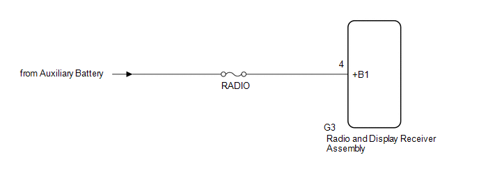 CAUTION / NOTICE / HINT NOTICE:
PROCEDURE
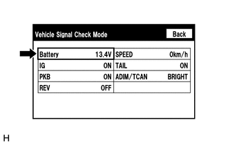
(b) Measure the auxiliary battery voltage. Standard Voltage: 11 to 15.5 V HINT: This display is updated once per second.
(a) Clear the DTCs. Body Electrical > Navigation System > Clear DTCs(b) Recheck for DTCs and check that no DTCs are output. Body Electrical > Navigation System > Trouble CodesOK: No DTCs are output.
(a) Disconnect the G3 radio and display receiver assembly connector. (b) Measure the voltage according to the value(s) in the table below. Standard Voltage:
|
Toyota Avalon (XX50) 2019-2022 Service & Repair Manual > Rear Stabilizer Bar: Inspection
INSPECTION PROCEDURE 1. INSPECT REAR STABILIZER LINK ASSEMBLY (a) Inspect the turning torque of the ball joint. (1) Secure the rear stabilizer link assembly in a vise using aluminum plates. NOTICE: Do not overtighten the vise. (2) Install the nut to the rear stabilizer link assembly stud. (3) Move t ...