DESCRIPTION This DTC is
stored when a communication error occurs between the radio and display
receiver assembly and combination meter assembly. |
DTC No. | Detection Item |
DTC Detection Condition | Trouble Area | |
B1324 | Lost Communication with Meter |
CAN reception error |
- Local bus communication line
- Combination meter power source circuit
- Radio and display receiver assembly
- Combination meter assembly
- Harness or connector
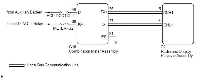
| WIRING DIAGRAM
 CAUTION / NOTICE / HINT
NOTICE:
- Depending on the parts that are replaced during vehicle inspection or
maintenance, performing initialization, registration or calibration may
be needed. Refer to Precaution for Audio and Visual System.
Click here 
- When replacing the radio and display receiver assembly, always replace
it with a new one. If a radio and display receiver assembly which was
installed to another vehicle is used, the following may occur:
- A communication malfunction DTC may be stored.
- The radio and display receiver assembly may not operate normally.
- Inspect the fuses for circuits related to this system before performing the following procedure.
PROCEDURE |
1. | CHECK HARNESS AND CONNECTOR (COMBINATION METER ASSEMBLY POWER SOURCE) |
(a) Disconnect the G16 combination meter assembly connector. (b) Measure the resistance according to the value(s) in the table below.
Standard Resistance: |
Tester Connection | Condition |
Specified Condition | |
G16-21 (ES) - Body ground |
Always | Below 1 Ω |
(c) Measure the voltage according to the value(s) in the table below. Standard Voltage: |
Tester Connection | Condition |
Specified Condition | |
G16-40 (B) - Body ground |
Power switch off | 11 to 14 V | |
G16-39 (IG+) - Body ground |
Power switch on (IG) |
11 to 14 V |
| NG |
 | REPAIR OR REPLACE HARNESS OR CONNECTOR |
|
OK |
 | |
| 2. |
CHECK HARNESS AND CONNECTOR | (a) Disconnect the cable from the negative (-) auxiliary battery terminal.
(b) Disconnect the G16 combination meter assembly connector. (c) Measure the resistance according to the value(s) in the table below.
Standard Resistance: |
Tester Connection | Condition |
Specified Condition | |
G16-36 (TX+) - G16-37 (TX-) |
Cable disconnected from negative (-) auxiliary battery terminal |
108 to 132 Ω |
| OK |
| REPLACE COMBINATION METER ASSEMBLY |
|
NG | |
| |
| 3. |
CHECK HARNESS AND CONNECTOR (RADIO AND DISPLAY RECEIVER ASSEMBLY - COMBINATION METER ASSEMBLY) |
(a) Disconnect the G2 radio and display receiver assembly connector. (b) Disconnect the G16 combination meter assembly connector.
(c) Measure the resistance according to the value(s) in the table below.
Standard Resistance: |
Tester Connection | Condition |
Specified Condition | |
G2-5 (CNH1) - G16-36 (TX+) |
Always | Below 1 Ω | |
G2-6 (CNL1) - G16-37 (TX-) |
Always | Below 1 Ω | |
G2-5 (CNH1) or G16-36 (TX+) - Body ground |
Always | 10 kΩ or higher | |
G2-6 (CNL1) or G16-37 (TX-) - Body ground |
Always | 10 kΩ or higher |
| OK |
| REPLACE RADIO AND DISPLAY RECEIVER ASSEMBLY |
| NG |
| REPAIR OR REPLACE HARNESS OR CONNECTOR | | 

