Components COMPONENTS ILLUSTRATION 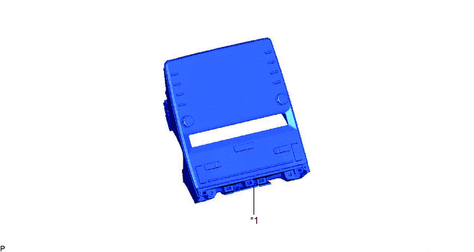
Inspection INSPECTION PROCEDURE 1. INSPECT HAZARD WARNING SWITCH ASSEMBLY (RADIO AND DISPLAY RECEIVER ASSEMBLY) 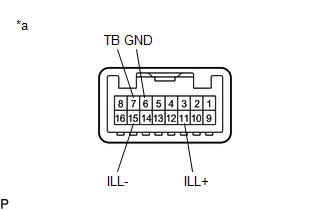
(a) Check the switch. (1) Measure the resistance according to the value(s) in the table below. Standard Resistance:
If the result is not as specified, replace the hazard warning switch assembly (radio and display receiver assembly). (b) Inspect the switch illumination. (1) Apply auxiliary battery voltage to the hazard warning switch assembly (radio and display receiver assembly) and check that the switch illuminates. OK:
If the result is not as specified, replace the hazard warning switch assembly (radio and display receiver assembly). Installation INSTALLATION PROCEDURE 1. INSTALL HAZARD WARNING SWITCH ASSEMBLY (RADIO AND DISPLAY RECEIVER ASSEMBLY) Click here Removal REMOVAL PROCEDURE 1. REMOVE HAZARD WARNING SWITCH ASSEMBLY (RADIO AND DISPLAY RECEIVER ASSEMBLY) Click here |
Toyota Avalon (XX50) 2019-2022 Service & Repair Manual > Blind Spot Monitor System(for Gasoline Model): Power Source Circuit
DESCRIPTION This circuit provides power to operate the blind spot monitor sensor. WIRING DIAGRAM CAUTION / NOTICE / HINT NOTICE: Inspect the fuses for circuits related to this system before performing the following procedure. PROCEDURE 1. CHECK HARNESS AND CONNECTOR (BLIND SPOT MONITOR SENSOR RH POW ...


