DESCRIPTION This circuit provides power to operate the blind spot monitor sensor. WIRING DIAGRAM 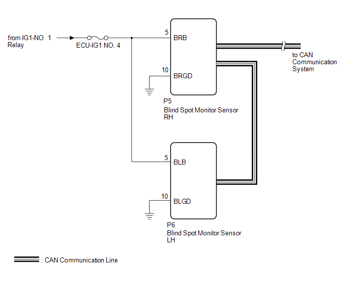 CAUTION / NOTICE / HINT NOTICE: Inspect the fuses for circuits related to this system before performing the following procedure. PROCEDURE
(a) Disconnect the P5 blind spot monitor sensor RH connector. (b) Measure the voltage according to the value(s) in the table below. Standard Voltage:
(a) Measure the resistance according to the value(s) in the table below. Standard Resistance:
(a) Disconnect the P6 blind spot monitor sensor LH connector. (b) Measure the voltage according to the value(s) in the table below. Standard Voltage:
(a) Measure the resistance according to the value(s) in the table below. Standard Resistance:
|
Toyota Avalon (XX50) 2019-2022 Service & Repair Manual > Intelligent Clearance Sonar System(for Gasoline Model): Operation Check
OPERATION CHECK ICS OFF INDICATOR LIGHT OPERATION CHECK (a) Turn the engine switch on (IG). (b) Turn the intelligent clearance sonar system off and confirm that the ICS OFF indicator in the combination meter illuminates. HINT: If the intelligent clearance sonar system is not set to off in the custom ...


