Components COMPONENTS ILLUSTRATION 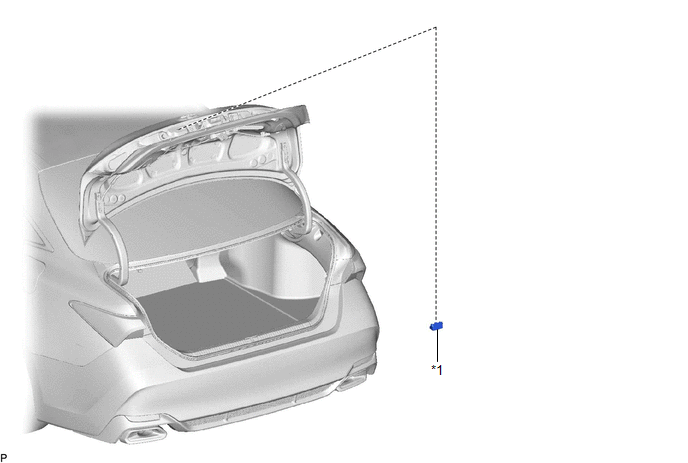
Inspection INSPECTION PROCEDURE 1. INSPECT LICENSE PLATE LIGHT ASSEMBLY 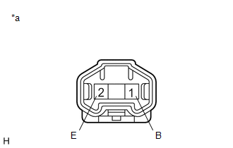
(a) Connect 4 dry-cell batteries (1.5 V) in series. NOTICE: Do not use rechargeable batteries as they may not output a voltage of 1.5 V. (b) Apply 6 V batter voltage to the terminals of the connector and check that the license plate light illuminates. OK:
If the result is not as specified, replace the license plate light assembly. Installation INSTALLATION CAUTION / NOTICE / HINT HINT:
PROCEDURE 1. INSTALL LICENSE PLATE LIGHT ASSEMBLY (a) Engage the 2 claws to install the license plate light assembly. (b) Connect the connector. 2. INSTALL LUGGAGE COMPARTMENT DOOR OUTSIDE GARNISH SUB-ASSEMBLY Click here
Removal REMOVAL CAUTION / NOTICE / HINT HINT:
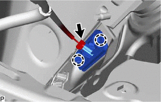
PROCEDURE 1. REMOVE LUGGAGE COMPARTMENT DOOR OUTSIDE GARNISH SUB-ASSEMBLY Click here 2. REMOVE LICENSE PLATE LIGHT ASSEMBLY
(b) Disengage the 2 claws to remove the license plate light assembly. |
Toyota Avalon (XX50) 2019-2022 Service & Repair Manual > Spiral Cable: Components
COMPONENTS ILLUSTRATION *A for HV Model - - *1 LUGGAGE TRIM SERVICE HOLE COVER - - ILLUSTRATION *1 HORN BUTTON ASSEMBLY *2 LOWER NO. 2 STEERING WHEEL COVER ILLUSTRATION *1 STEERING WHEEL ASSEMBLY - - Tightening torque for "Major areas involving basic vehicle performance such as moving/turning/stoppi ...