INSTALLATION PROCEDURE 1. INSTALL NO. 2 ANTENNA CORD SUB-ASSEMBLY (w/ Manual (SOS) Switch) (a) Engage the 4 clamps to install the No. 2 antenna cord sub-assembly. (b) Connect the connector. 2. INSTALL NO. 3 ANTENNA CORD SUB-ASSEMBLY HINT: Butyl tape and adhesive tape are not available as supply parts. If these pieces of tape still have enough adhesion to secure the No. 3 antenna cord sub-assembly to the roof headlining assembly, reuse them. If the adhesive tape and/or the butyl tape is no longer sticky, apply new tape following the procedure below. (a) Apply new butyl tape. for Normal Roof: 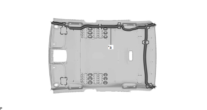
for Moon Roof: 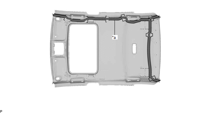
(1) Remove the old butyl tape from the roof headlining assembly. (2) Prepare an appropriate amount of new butyl tape. HINT: Be careful not to touch the adhesive surface. (3) Apply the butyl tape to the roof headlining assembly while aligning the tape with the markings on the roof headlining assembly. (4) Peel off the release paper from the butyl tape. (b) Align the marking tape (A) on the No. 3 antenna cord sub-assembly with the protrusion on the front of the roof headlining assembly and wrap tape around the No. 3 antenna cord sub-assembly and protrusion of the roof headlining assembly. for Normal Roof: 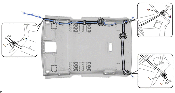
for Moon Roof: 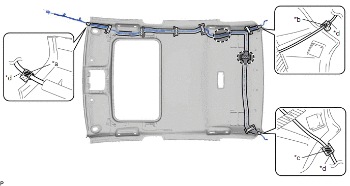
(c) Align the marking tape (B) on the No. 3 antenna cord sub-assembly with the protrusion on the rear of the roof headlining assembly and wrap tape around the No. 3 antenna cord sub-assembly and protrusion of the roof headlining assembly. (d) Align the marking tape (C) on the No. 3 antenna cord sub-assembly with the protrusion on the rear of the roof headlining assembly and wrap tape around the No. 3 antenna cord sub-assembly and protrusion of the roof headlining assembly. (e) Install the No. 3 antenna cord sub-assembly to the roof headlining assembly. NOTICE:
HINT: Secure the extra length of the No. 3 antenna cord sub-assembly in the adjustment area. (f) Apply the adhesive tape as shown in the illustration to secure the No. 3 antenna cord sub-assembly. 3. INSTALL ROOF HEADLINING ASSEMBLY Click here
4. INSTALL NO. 4 ANTENNA CORD SUB-ASSEMBLY (a) Engage the 8 clamps to install the No. 4 antenna cord sub-assembly. (b) Engage the 2 claws. (c) Connect the connector. 5. INSTALL NO. 3 HEATER TO REGISTER DUCT SUB-ASSEMBLY Click here 6. INSTALL DEFROSTER NOZZLE ASSEMBLY Click here 7. INSTALL NO. 2 SIDE DEFROSTER NOZZLE DUCT Click here 8. INSTALL NO. 1 SIDE DEFROSTER NOZZLE DUCT Click here 9. INSTALL INSTRUMENT PANEL SAFETY PAD SUB-ASSEMBLY Click here |
Toyota Avalon (XX50) 2019-2022 Service & Repair Manual > Intelligent Clearance Sonar System(for Gasoline Model): G Sensor Failure (C1647)
DESCRIPTION The clearance warning sonar ECU assembly communicates with the airbag ECU assembly (yaw rate and acceleration sensor) via CAN communication, and if it is determined that the airbag ECU assembly (yaw rate and acceleration sensor) is malfunctioning, DTC C1647 is stored. DTC No. Detection I ...


