REMOVAL CAUTION / NOTICE / HINT The necessary procedures (adjustment, calibration, initialization, or registration) that must be performed after parts are removed and installed, or replaced during antenna cord sub-assembly removal/installation are shown below. Necessary Procedure After Parts Removed/Installed/Replaced (for Gasoline Model)
CAUTION: Some of these service operations affect the SRS airbag system. Read the precautionary notices concerning the SRS airbag system before servicing. Click here
 Necessary Procedure After Parts Removed/Installed/Replaced (for HV Model) Necessary Procedure After Parts Removed/Installed/Replaced (for HV Model)
CAUTION: Some of these service operations affect the SRS airbag system. Read the precautionary notices concerning the SRS airbag system before servicing. Click here
PROCEDURE 1. REMOVE INSTRUMENT PANEL SAFETY PAD SUB-ASSEMBLY Click here
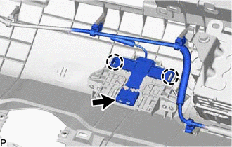
2. REMOVE NO. 1 SIDE DEFROSTER NOZZLE DUCT Click here 3. REMOVE NO. 2 SIDE DEFROSTER NOZZLE DUCT Click here 4. REMOVE DEFROSTER NOZZLE ASSEMBLY Click here 5. REMOVE NO. 3 HEATER TO REGISTER DUCT SUB-ASSEMBLY Click here 6. REMOVE NO. 4 ANTENNA CORD SUB-ASSEMBLY
(b) Disengage the 2 claws.
7. REMOVE ROOF HEADLINING ASSEMBLY Click here
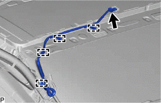
8. REMOVE NO. 3 ANTENNA CORD SUB-ASSEMBLY (a) Remove the adhesive tape from the roof headlining assembly. for Normal Roof: 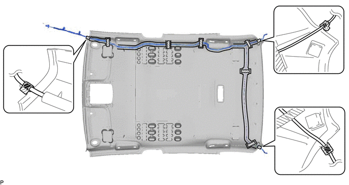
for Moon Roof: 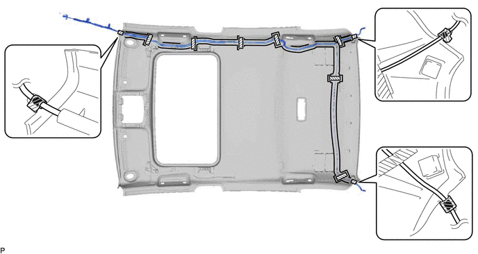
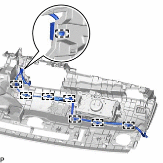
(b) Remove the No. 3 antenna cord sub-assembly from the roof headlining assembly. 9. REMOVE NO. 2 ANTENNA CORD SUB-ASSEMBLY (w/ Manual (SOS) Switch)
(b) Disengage the 4 clamps to remove the No. 2 antenna cord sub-assembly. | |||||||||||||||||||||||||||||||||||||||||||||||||||||||||||||||||
Toyota Avalon (XX50) 2019-2022 Service & Repair Manual > Wiper / Washer: Relay
On-vehicle InspectionON-VEHICLE INSPECTION PROCEDURE 1. INSPECT WIPER RELAY (a) Measure the resistance according to the value(s) in the table below. Standard Resistance: Tester Connection Condition Specified Condition 3 - 5 Auxiliary battery voltage not applied between terminals 1 and 2 10 kΩ or h ...