REMOVAL CAUTION / NOTICE / HINT The necessary procedures (adjustment, calibration, initialization, or registration) that must be performed after parts are removed and installed, or replaced during telephone antenna assembly removal/installation are shown below. Necessary Procedure After Parts Removed/Installed/Replaced (for Gasoline Model)
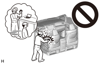
CAUTION: Some of these service operations affect the SRS airbag system. Read the precautionary notices concerning the SRS airbag system before servicing. Click here
 Necessary Procedure After Parts Removed/Installed/Replaced (for HV Model) Necessary Procedure After Parts Removed/Installed/Replaced (for HV Model)
CAUTION: Some of these service operations affect the SRS airbag system. Read the precautionary notices concerning the SRS airbag system before servicing. Click here
PROCEDURE 1. REMOVE ROOF HEADLINING ASSEMBLY Click here
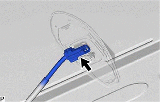
2. REMOVE TELEPHONE ANTENNA ASSEMBLY WITH COVER
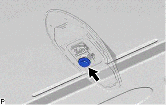
(c) Remove the washer and holder as shown in the illustration. 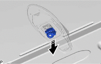
(d) Remove the telephone antenna assembly with cover as shown in the illustration. 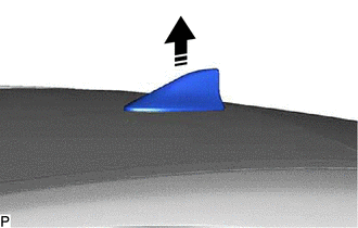
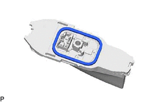
3. REMOVE TELEPHONE ANTENNA ASSEMBLY (a) Pull the telephone antenna assembly in the direction indicated by the arrow (1) shown in the illustration to disengage the 3 claws and 2 guides. 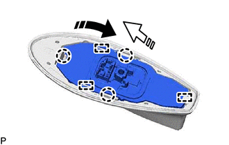
(b) Pull the telephone antenna assembly in the direction indicated by the arrow (2) shown in the illustration to disengage the guide and remove the telephone antenna assembly. (c) When reusing the telephone antenna assembly:
| |||||||||||||||||||||||||||||||||||||||||||||||||||||||||||||||||
Toyota Avalon (XX50) 2019-2022 Service & Repair Manual > Sfi System: Cylinder 1 Injector "A" Circuit Open (P020113-P020413,P062D13)
DESCRIPTION The D-4S system has two fuel injection systems. One is an in-cylinder direct injection system that directly injects pressurized fuel into the combustion chamber. The other is an intake port injection system. The ECM determines which fuel injection system to use in accordance with the eng ...