INSTALLATION PROCEDURE 1. INSTALL INSTRUMENT PANEL SAFETY PAD SUB-ASSEMBLY (a) Engage the 5 guides as shown in the illustration to temporarily install the instrument panel safety pad sub-assembly. 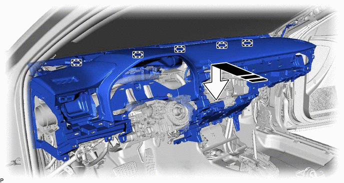
NOTICE:
(b) Install the instrument panel safety pad sub-assembly with the 4 bolts <B>, 2 bolts <A> and nut <E>. Torque: Bolt<A> : 20 N·m {204 kgf·cm, 15 ft·lbf} (c) Install the 2 clips. (d) Engage each clamp. (e) Connect each connector. (f) Engage the 2 claws to connect the cooler (room temp. sensor) thermistor. 2. CONNECT NO. 2 INSTRUMENT PANEL WIRE Click here
3. INSTALL TURN SIGNAL SWITCH Click here
4. INSTALL WINDSHIELD WIPER SWITCH ASSEMBLY Click here 5. INSTALL UPPER STEERING COLUMN COVER for Manual Tilt and Manual Telescopic Steering Column: Click here
for Power Tilt and Power Telescopic Steering Column: Click here
6. INSTALL LOWER STEERING COLUMN COVER for Manual Tilt and Manual Telescopic Steering Column: Click here
for Power Tilt and Power Telescopic Steering Column: Click here
7. ALIGN FRONT WHEELS FACING STRAIGHT AHEAD 8. INSPECT AND ADJUST SPIRAL CABLE WITH SENSOR SUB-ASSEMBLY Click here
9. INSTALL STEERING WHEEL ASSEMBLY Click here 10. CHECK STEERING WHEEL CENTER POINT 11. INSTALL HORN BUTTON ASSEMBLY Click here
12. INSTALL FRONT NO. 2 SPEAKER ASSEMBLY (for RH Side) Click here 13. INSTALL FRONT NO. 4 SPEAKER ASSEMBLY (for 14 Speakers) Click here 14. INSTALL FRONT NO. 2 SPEAKER ASSEMBLY (for LH Side) Click here 15. INSTALL NO. 1 DEFROSTER NOZZLE GARNISH (a) Connect the connector. (b) Engage the 9 guides, 9 clips and 2 claws as shown in the illustration to install the No. 1 defroster nozzle garnish. 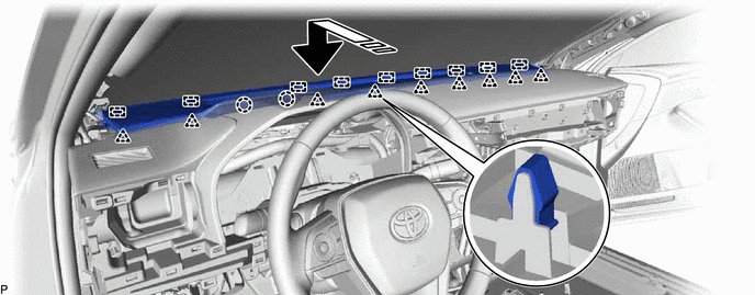
16. INSTALL FRONT PILLAR GARNISH RH HINT: Use the same procedure as for the LH side. Click here 17. INSTALL FRONT PILLAR GARNISH LH Click here 18. INSTALL NO. 2 INSTRUMENT CLUSTER MOULDING (a) Engage the 2 clips as shown in the illustration to install the No. 2 instrument cluster moulding. 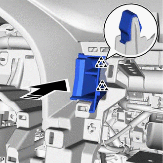
19. INSTALL NO. 3 INSTRUMENT CLUSTER FINISH PANEL GARNISH (a) Engage the 2 clips as shown in the illustration to install the No. 3 instrument cluster finish panel garnish. 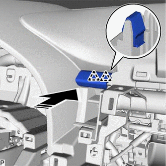
20. INSTALL NO. 1 INSTRUMENT PANEL REGISTER ASSEMBLY (a) Engage the 4 clips as shown in the illustration to install the No. 1 instrument panel register assembly. 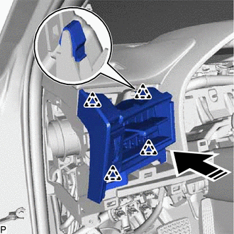
21. INSTALL NO. 1 INSTRUMENT CLUSTER FINISH PANEL GARNISH (a) Engage the 2 guides and 2 clips as shown in the illustration to install the No. 1 instrument cluster finish panel garnish. 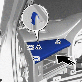
22. INSTALL COMBINATION METER ASSEMBLY Click here 23. INSTALL INSTRUMENT CLUSTER FINISH PANEL SUB-ASSEMBLY (a) Engage the 2 guides and 2 clips as shown in the illustration. 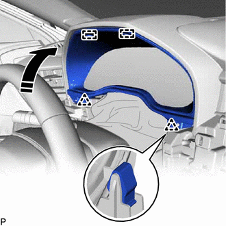
(b) Install the 2 clips. (c) Engage the 2 guides and 4 clips as shown in the illustration to install the instrument cluster finish panel sub-assembly. 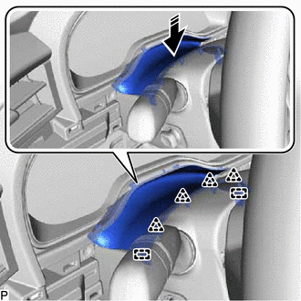
24. INSTALL NO. 1 INSTRUMENT PANEL GARNISH SUB-ASSEMBLY (a) Engage the 5 clips as shown in the illustration to install the No. 1 instrument panel garnish sub-assembly. 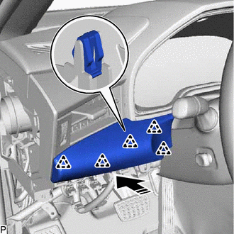
25. INSTALL LOWER INSTRUMENT PANEL FINISH PANEL ASSEMBLY (a) Connect the connector. (b) Engage the 4 clips as shown in the illustration to install the lower instrument panel finish panel assembly. 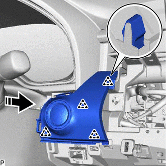
26. INSTALL INSTRUMENT CLUSTER FINISH PANEL GARNISH ASSEMBLY (a) Engage the 2 clips and claw as shown in the illustration to install the instrument cluster finish panel garnish assembly. 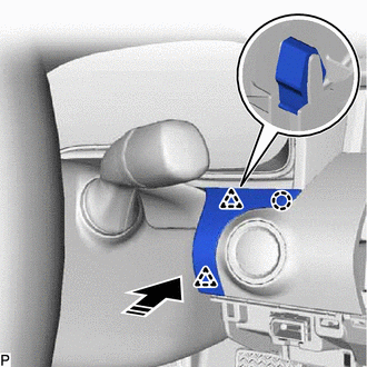
27. INSTALL NO. 4 INSTRUMENT PANEL REGISTER ASSEMBLY (a) Engage the 9 clips as shown in the illustration. 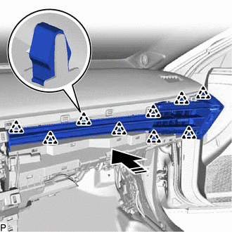
(b) Install the No. 4 instrument panel register assembly with the screw <D>. 28. INSTALL NO. 2 INSTRUMENT CLUSTER FINISH PANEL GARNISH (a) Engage the 2 guides and 5 clips as shown in the illustration to install the No. 2 instrument cluster finish panel garnish. 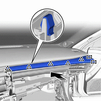
29. INSTALL NO. 2 INSTRUMENT PANEL GARNISH SUB-ASSEMBLY (a) Engage the 10 clips as shown in the illustration. 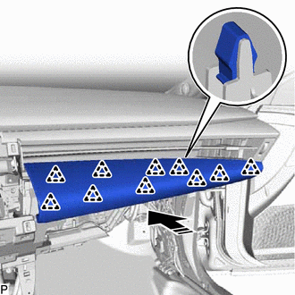
(b) Install the No. 2 instrument panel garnish sub-assembly with the screw <D>. 30. INSTALL LOWER CENTER INSTRUMENT PANEL FINISH PANEL (a) Engage the 8 clips as shown in the illustration to install the lower center instrument panel finish panel. 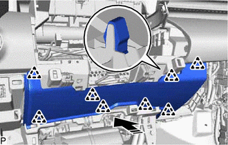
31. INSTALL LOWER INSTRUMENT PANEL SUB-ASSEMBLY (a) Connect the connector and engage the clamp. (b) Engage the 3 clips as shown in the illustration. 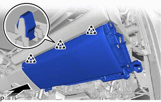
(c) Install the lower instrument panel sub-assembly with the 5 screws <C>. 32. INSTALL LOWER NO. 2 INSTRUMENT PANEL AIRBAG ASSEMBLY Click here
33. INSTALL INSTRUMENT SIDE PANEL RH (a) Insert the instrument side panel RH in the direction indicated by the arrow (1) shown in the illustration to engage the 3 guides. 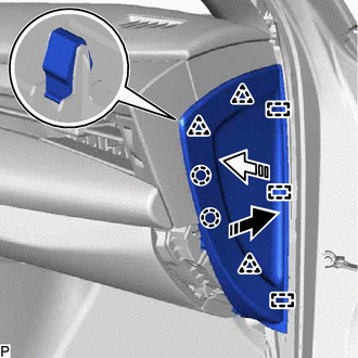
(b) Push the instrument side panel RH in the direction indicated by the arrow (2) shown in the illustration to engage the 3 clips and 2 claws and install it. 34. INSTALL FRONT DOOR OPENING TRIM WEATHERSTRIP RH Click here 35. INSTALL GLOVE COMPARTMENT PLATE (a) Engage the 4 clips as shown in the illustration to install the glove compartment plate. 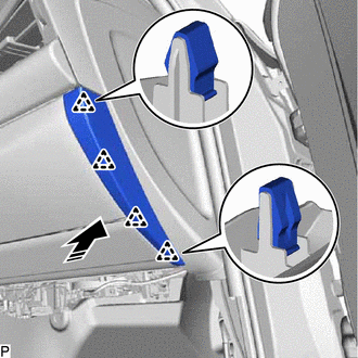
36. INSTALL NO. 2 INSTRUMENT PANEL UNDER COVER SUB-ASSEMBLY (a) Connect the connector. (b) Engage the clamp. (c) Engage the 2 guides as shown in the illustration. 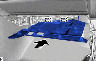
(d) Engage the 4 claws as shown in the illustration to install the No. 2 instrument panel under cover sub-assembly. 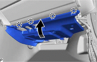
37. INSTALL COWL SIDE TRIM SUB-ASSEMBLY RH HINT: Use the same procedure as for the LH side. Click here
38. INSTALL FRONT DOOR SCUFF PLATE RH HINT: Use the same procedure as for the LH side. Click here
39. INSTALL NO. 2 HEATER TO REGISTER DUCT SUB-ASSEMBLY (a) Install the No. 2 heater to register duct sub-assembly with the 2 screws <C>. 40. INSTALL RADIO AND DISPLAY RECEIVER ASSEMBLY WITH BRACKET Click here
41. INSTALL CENTER NO. 2 INSTRUMENT CLUSTER FINISH PANEL (a) Engage the guide and 5 claws as shown in the illustration to install the center No. 2 instrument cluster finish panel. 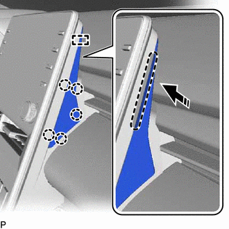
42. INSTALL CENTER NO. 1 INSTRUMENT CLUSTER FINISH PANEL (a) Engage the clip and 2 claws as shown in the illustration to install the center No. 1 instrument cluster finish panel. 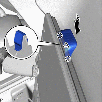
43. INSTALL LOWER NO. 1 INSTRUMENT PANEL AIRBAG ASSEMBLY Click here 44. INSTALL LOWER NO. 2 INSTRUMENT PANEL FINISH PANEL (a) Engage the 6 clips as shown in the illustration to install the lower No. 2 instrument panel finish panel. 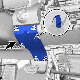
45. INSTALL NO. 1 INSTRUMENT PANEL SUB-ASSEMBLY (a) Connect each connector. (b) Engage the clamp. (c) Engage the 6 clips as shown in the illustration to install the No. 1 instrument panel sub-assembly. 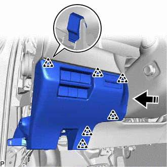
46. CONNECT HOOD LOCK CONTROL LEVER SUB-ASSEMBLY (a) Engage the claw and 2 guides to connect the hood lock control lever sub-assembly. 47. INSTALL NO. 1 INSTRUMENT PANEL UNDER COVER SUB-ASSEMBLY (a) Connect the connector and engage the 2 clamps. (b) Engage the 2 claws to install the DLC3 connector. (c) Engage the 2 guides and 2 claws as shown in the illustration. 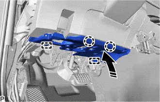
(d) Install the No. 1 instrument panel under cover sub-assembly with the 2 screws <C>. 48. INSTALL INSTRUMENT SIDE PANEL LH (a) Insert the instrument side panel LH in the direction indicated by the arrow (1) shown in the illustration to engage the 3 guides. 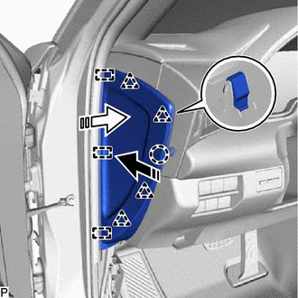
(b) Push the instrument side panel LH in the direction indicated by the arrow (2) shown in the illustration to engage the 4 clips and claw and install it. 49. INSTALL FRONT DOOR OPENING TRIM WEATHERSTRIP LH Click here
50. INSTALL COWL SIDE TRIM SUB-ASSEMBLY LH Click here 51. INSTALL FRONT DOOR SCUFF PLATE LH Click here 52. INSTALL CONSOLE ASSEMBLY Click here |
Toyota Avalon (XX50) 2019-2022 Service & Repair Manual > Sfi System: Intake Air Temperature Sensor 1 Bank 1 Signal Stuck in Range (P01102A)
DESCRIPTION Refer to DTC P011011. Click here DTC No. Detection Item DTC Detection Condition Trouble Area MIL Memory Note P01102A Intake Air Temperature Sensor 1 Bank 1 Signal Stuck in Range Either of the following conditions is met (2 trip detection logic): The intake air temperature change from the ...


