Components COMPONENTS ILLUSTRATION 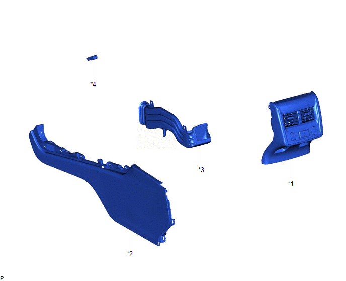
Inspection INSPECTION PROCEDURE 1. INSPECT NO. 5 INTERIOR ILLUMINATION LIGHT SUB-ASSEMBLY 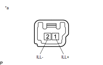
(a) Apply auxiliary battery voltage to the No. 5 interior illumination light sub-assembly and check that the light illuminates. OK:
If the result is not as specified, replace the No. 5 interior illumination light sub-assembly. Installation INSTALLATION PROCEDURE 1. INSTALL NO. 5 INTERIOR ILLUMINATION LIGHT SUB-ASSEMBLY (a) Turn the No. 5 interior illumination light sub-assembly as shown in the illustration to install it. 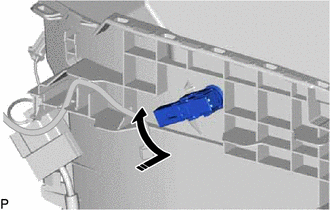
(b) Connect the connector. 2. INSTALL NO. 3 CONSOLE BOX DUCT Click here
3. INSTALL NO. 2 BOX SIDE PANEL Click here
4. INSTALL CONSOLE REAR END PANEL SUB-ASSEMBLY Click here 5. INSTALL CONSOLE ASSEMBLY Click here Removal REMOVAL PROCEDURE 1. REMOVE CONSOLE ASSEMBLY Click here 2. REMOVE CONSOLE REAR END PANEL SUB-ASSEMBLY Click here
3. REMOVE NO. 2 BOX SIDE PANEL Click here
4. REMOVE NO. 3 CONSOLE BOX DUCT Click here
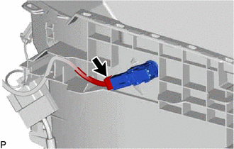
5. REMOVE NO. 5 INTERIOR ILLUMINATION LIGHT SUB-ASSEMBLY
(b) Turn the No. 5 interior illumination light sub-assembly as shown in the illustration to remove it. 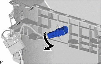
|
Toyota Avalon (XX50) 2019-2022 Service & Repair Manual > Door Lock: Door Control Transmitter
ComponentsCOMPONENTS ILLUSTRATION *1 TRANSMITTER BATTERY *2 MECHANICAL KEY *3 TRANSMITTER HOUSING COVER *4 TRANSMITTER HOUSING CASE *5 SMART KEY DOOR CONTROL TRANSMITTER HOUSING SET - - InspectionINSPECTION PROCEDURE 1. INSPECT ELECTRICAL KEY TRANSMITTER SUB-ASSEMBLY (a) Inspect the operation of th ...