Components COMPONENTS ILLUSTRATION 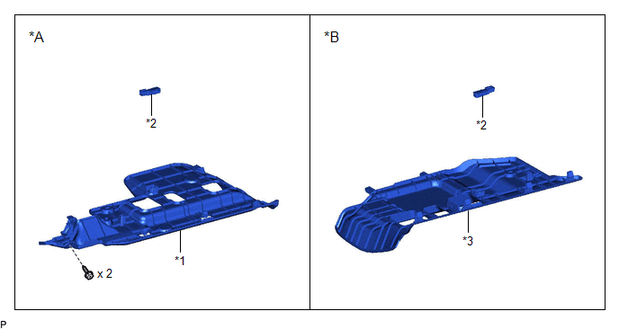
Inspection INSPECTION PROCEDURE 1. INSPECT NO. 1 INTERIOR ILLUMINATION LIGHT ASSEMBLY 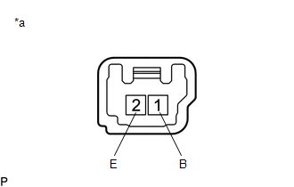
(a) Apply auxiliary battery voltage to the No. 1 interior illumination light assembly and check that the light illuminates. OK:
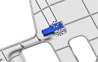
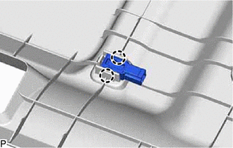
If the result is not as specified, replace the No. 1 interior illumination light assembly. Installation INSTALLATION PROCEDURE 1. INSTALL NO. 1 INTERIOR ILLUMINATION LIGHT ASSEMBLY (a) Engage the 2 claws to install the No. 1 interior illumination light assembly. 2. INSTALL NO. 1 INSTRUMENT PANEL UNDER COVER SUB-ASSEMBLY (for Driver Side) Click here 3. INSTALL NO. 2 INSTRUMENT PANEL UNDER COVER SUB-ASSEMBLY (for Front Passenger Side) Click here Removal REMOVAL PROCEDURE 1. REMOVE NO. 1 INSTRUMENT PANEL UNDER COVER SUB-ASSEMBLY (for Driver Side) Click here 2. REMOVE NO. 2 INSTRUMENT PANEL UNDER COVER SUB-ASSEMBLY (for Front Passenger Side) Click here 3. REMOVE NO. 1 INTERIOR ILLUMINATION LIGHT ASSEMBLY (a) for Driver Side:
(b) for Front Passenger Side:
|
Toyota Avalon (XX50) 2019-2022 Service & Repair Manual > Electronically Controlled Brake System(for Gasoline Model): Brake Hold Standby Indicator Light Circuit
DESCRIPTION The brake hold standby indicator light turns on if brake hold control is possible when the following conditions required for operation standby are met and the brake hold switch (electric parking brake switch assembly) is pressed while the engine switch is on (IG). Conditions required for ...