Toyota Avalon (XX50) 2019-2022 Service & Repair Manual: Manual Button Malfunction (B15C5)

DESCRIPTION

This DTC is set when the DCM (Telematics Transceiver) detects an open or short circuit in the manual (SOS) switch.

DTC No.

Detection Item

DTC Detection Condition

Trouble Area

B15C5

Manual Button Malfunction

Open or short circuit in manual (SOS) switch is detected.

  • DCM (Telematics Transceiver)
  • Roof console box sub-assembly
  • Wire harness or connector

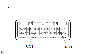
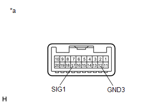
WIRING DIAGRAM

w/o Sliding Roof
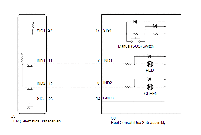
 w/ Sliding Roof

CAUTION / NOTICE / HINT

HINT:

Before performing this diagnostic procedure, make sure to perform Health Check and confirm that the DCM/VIN registration information is correct.

Click here

PROCEDURE

1.

CONFIRM MODEL

(a) Choose the model to be inspected.

Result

Proceed to

w/ Sliding Roof

A

w/o Sliding Roof

B

B

GO TO STEP 6

A

2.

CHECK DTC

(a) Turn the engine switch off.

(b) Connect the Techstream to the DLC3.

(c) Turn the engine switch on (IG) and wait for 10 seconds.

(d) Turn the Techstream on.

(e) Clear the DTCs.

Body Electrical > Telematics > Clear DTCs

(f) Recheck for DTCs.

Body Electrical > Telematics > Trouble Codes

Result

Proceed to

DTC B1570, B1571 and B15C5 are output

A

DTC B15C5 is output

(DTC B1570 and B1571 are not output)

B

B

USE SIMULATION METHOD TO CHECK

A

3.

INSPECT ROOF CONSOLE BOX SUB-ASSEMBLY (MANUAL (SOS) SWITCH)

(a) Disconnect the O10 roof console box sub-assembly connector.

*a

Component without harness connected

(Roof Console Box Sub-assembly)

(b) Measure the resistance according to the value(s) in the table below.

Standard Resistance:

Tester Connection

Condition

Specified Condition

24 (SIG1) - 16 (GND3)

Manual (SOS) switch not pressed

410 to 414 Ω

24 (SIG1) - 16 (GND3)

Manual (SOS) switch pressed

81 to 83 Ω

NG

REPLACE ROOF CONSOLE BOX SUB-ASSEMBLY

OK

4.

CHECK HARNESS AND CONNECTOR (DCM (TELEMATICS TRANSCEIVER) - ROOF CONSOLE BOX SUB-ASSEMBLY)

(a) Disconnect the G9 DCM (Telematics Transceiver) connector.

(b) Disconnect the O10 roof console box sub-assembly connector.

(c) Measure the resistance according to the value(s) in the table below.

Standard Resistance:

Tester Connection

Condition

Specified Condition

G9-26 (SIG-) - O10-16 (GND3)

Always

Below 1 Ω

G9-26 (SIG-) or O10-16 (GND3) - Body ground

Always

10 kΩ or higher

G9-27 (SIG1) - O10-24 (SIG1)

Always

Below 1 Ω

G9-27 (SIG1) or O10-24 (SIG1) - Body ground

Always

10 kΩ or higher

NG

REPAIR OR REPLACE HARNESS OR CONNECTOR

OK

5.

REPLACE DCM (TELEMATICS TRANSCEIVER)

(a) Replace the DCM (Telematics Transceiver).

Click here

NOTICE:

  • The engine switch must be off.
  • Do not swap the DCM (Telematics Transceiver) with one from another vehicle.
NEXT

PERFORM DCM ACTIVATION

6.

CHECK DTC

(a) Turn the engine switch off.

(b) Connect the Techstream to the DLC3.

(c) Turn the engine switch on (IG) and wait for 10 seconds.

(d) Turn the Techstream on.

(e) Clear the DTCs.

Body Electrical > Telematics > Clear DTCs

(f) Recheck for DTCs.

Body Electrical > Telematics > Trouble Codes

Result

Proceed to

DTC B1570, B1571 and B15C5 are output

A

DTC B15C5 is output

(DTC B1570 and B1571 are not output)

B

B

USE SIMULATION METHOD TO CHECK

A

7.

INSPECT ROOF CONSOLE BOX SUB-ASSEMBLY (MANUAL (SOS) SWITCH)

(a) Disconnect the O9 roof console box sub-assembly connector.

*a

Component without harness connected

(Roof Console Box Sub-assembly)

(b) Measure the resistance according to the value(s) in the table below.

Standard Resistance:

Tester Connection

Condition

Specified Condition

17 (SIG1) - 12 (GND3)

Manual (SOS) switch not pressed

410 to 414 Ω

17 (SIG1) - 12 (GND3)

Manual (SOS) switch pressed

81 to 83 Ω

NG

REPLACE ROOF CONSOLE BOX SUB-ASSEMBLY

OK

8.

CHECK HARNESS AND CONNECTOR (DCM (TELEMATICS TRANSCEIVER) - ROOF CONSOLE BOX SUB-ASSEMBLY)

(a) Disconnect the G9 DCM (Telematics Transceiver) connector.

(b) Disconnect the O9 roof console box sub-assembly connector.

(c) Measure the resistance according to the value(s) in the table below.

Standard Resistance:

Tester Connection

Condition

Specified Condition

G9-26 (SIG-) - O9-12 (GND3)

Always

Below 1 Ω

G9-26 (SIG-) or O9-12 (GND3) - Body ground

Always

10 kΩ or higher

G9-27 (SIG1) - O9-17 (SIG1)

Always

Below 1 Ω

G9-27 (SIG1) or O9-17 (SIG1) - Body ground

Always

10 kΩ or higher

NG

REPAIR OR REPLACE HARNESS OR CONNECTOR

OK

9.

REPLACE DCM (TELEMATICS TRANSCEIVER)

(a) Replace the DCM (Telematics Transceiver).

Click here

NOTICE:

  • The engine switch must be off.
  • Do not swap the DCM (Telematics Transceiver) with one from another vehicle.
NEXT

PERFORM DCM ACTIVATION

    Airbag Signal Malfunction/Not Input (B15C4)

    Backup Battery Failure (B15CC)

    See More:

    Toyota Avalon (XX50) 2019-2022 Service & Repair Manual > Hybrid Control System: Transmission Fluid Temperature Sensor "C" Circuit Short to Ground (P274A11,P274A15)
    DTC SUMMARY MALFUNCTION DESCRIPTION These DTCs are stored when the transmission fluid temperature sensor output is abnormal. The cause of this malfunction may be one of the following: Hybrid vehicle control ECU malfunction Hybrid vehicle control ECU internal malfunction Transmission fluid temperatur ...

    Toyota Avalon (XX50) 2019-2022 Owners Manual

    Toyota Avalon (XX50) 2019-2022 Service & Repair Manual

    © 2024 Copyright www.tavalon.net
    0.017