Components COMPONENTS ILLUSTRATION 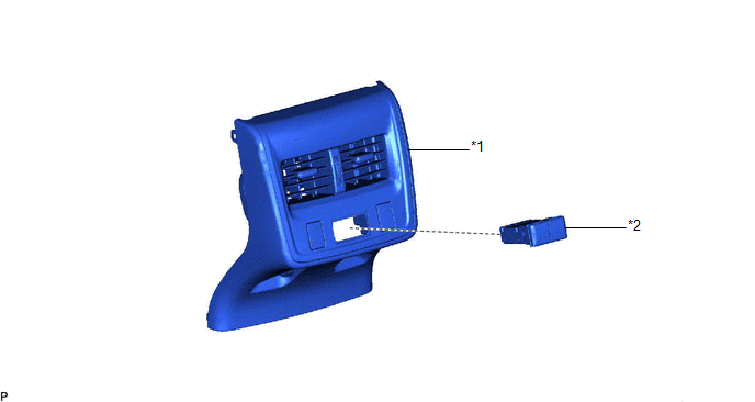
Installation INSTALLATION PROCEDURE 1. INSTALL USB CHARGER SOCKET (a) Engage the 4 claws to install the USB charger socket as shown in the illustration. 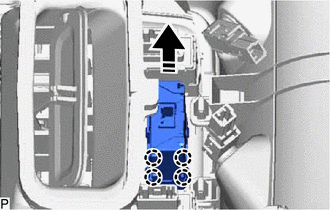
2. INSTALL CONSOLE REAR END PANEL SUB-ASSEMBLY Click here
Removal REMOVAL PROCEDURE 1. REMOVE CONSOLE REAR END PANEL SUB-ASSEMBLY Click here
2. REMOVE USB CHARGER SOCKET (a) Using a screwdriver with its tip wrapped with protective tape, disengage the 4 claws and remove the USB charger socket as shown in the illustration. 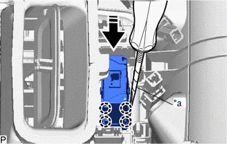
|
Toyota Avalon (XX50) 2019-2022 Service & Repair Manual > Ambient Temperature Sensor(for 2gr-fks): Inspection
INSPECTION PROCEDURE 1. INSPECT THERMISTOR ASSEMBLY (a) Measure the resistance according to the value(s) in the table below. Standard Resistance: Tester Connection Condition Specified Condition 1 - 2 10°C (50°F) 3.00 to 3.73 kΩ 15°C (59°F) 2.45 to 2.88 kΩ 20°C (68°F) 1.95 to 2.30 kΩ 25°C ( ...


