PARTS LOCATION ILLUSTRATION 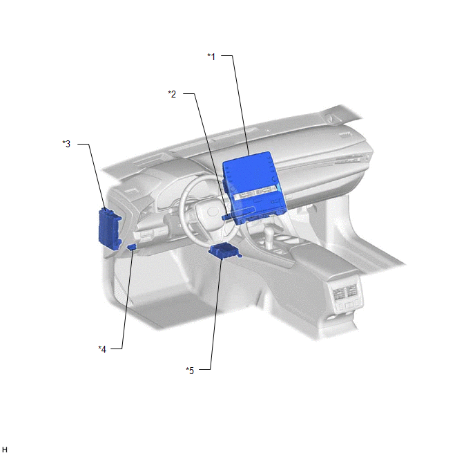
ILLUSTRATION 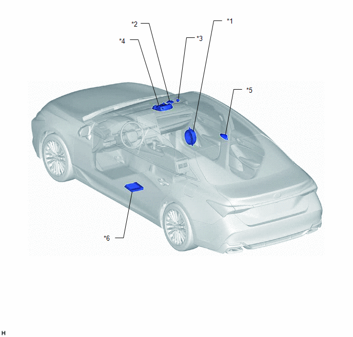
ILLUSTRATION 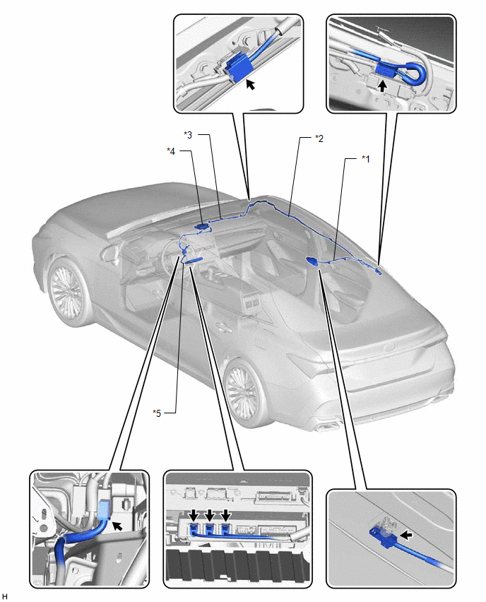
|
Toyota Avalon (XX50) 2019-2022 Service & Repair Manual > Luggage Compartment Door: Disassembly
DISASSEMBLY CAUTION / NOTICE / HINT The necessary procedures (adjustment, calibration, initialization, or registration) that must be performed after parts are removed and installed, or replaced during luggage compartment door rmoval/installation are shown below. Necessary Procedure After Parts Remov ...


